
A review of worm-like pipe inspection robots: research, trends and challenges
 0
0Abstract
In recent years, the development of worm-like robots has increased significantly. These robots use peristaltic motion comprised of radial expansion and axial elongation to move leglessly through their environments. Soft worm-like robots have the advantage of conforming to their environment, making them ideal for confined spaces such as pipelines which are essential to societal infrastructure. Pipeline contamination and corrosion can be detrimental and costly and thus regular checking is vital. Some pipes are difficult to access due to size, access restrictions and harmful waste contamination (such as in nuclear power plants). This has led to an increase of research into soft worm-like robots for pipe inspection. This review will analyse the recent progress in this area to assess current robotic capabilities and where work may be further needed to ensure they are applicable to real-world applications.
Keywords
INTRODUCTION
Pipelines are relied on for their ability to transport substances economically and quickly such as water, gas, oil, and waste products. Any breakages or blockages in them can be incredibly harmful to businesses and infrastructures; hence, they are required to be well maintained. This typically involves periodic inspection for signs of damage and potential blockages. Often, these pipes are difficult and dangerous to access for humans, and thus, a robotic solution is required. In recent years, considerable research has delved into the use of in-pipe inspection robots (IPIRs) to aid in this maintenance[1]. For large-diameter pipelines,
Snakes and annelids use a wriggling or worming motion to shift their body through soil or uneven terrain and can form complex shapes to fit their surroundings. Hence, they are the common inspiration for soft robots designed to move in constrained environments such as pipe structures[5-9]. Another example of bioinspiration applicable to constrained environments is vine or everting robots, which can travel into confined spaces by growing through the tip[10]. Earthworms create forward movement by contracting and extending their body segments to create a wave-like motion[8] [Figure 1]. This pattern of contraction and extension from front to rear is called peristalsis and can be seen in other annelids and legless insects[11]. On the other hand, inchworms use an inching motion to propel themselves forward by anchoring the surface with the front of their body whilst contracting the middle and then extending their middle whilst anchoring the surface with the back of the body[12].
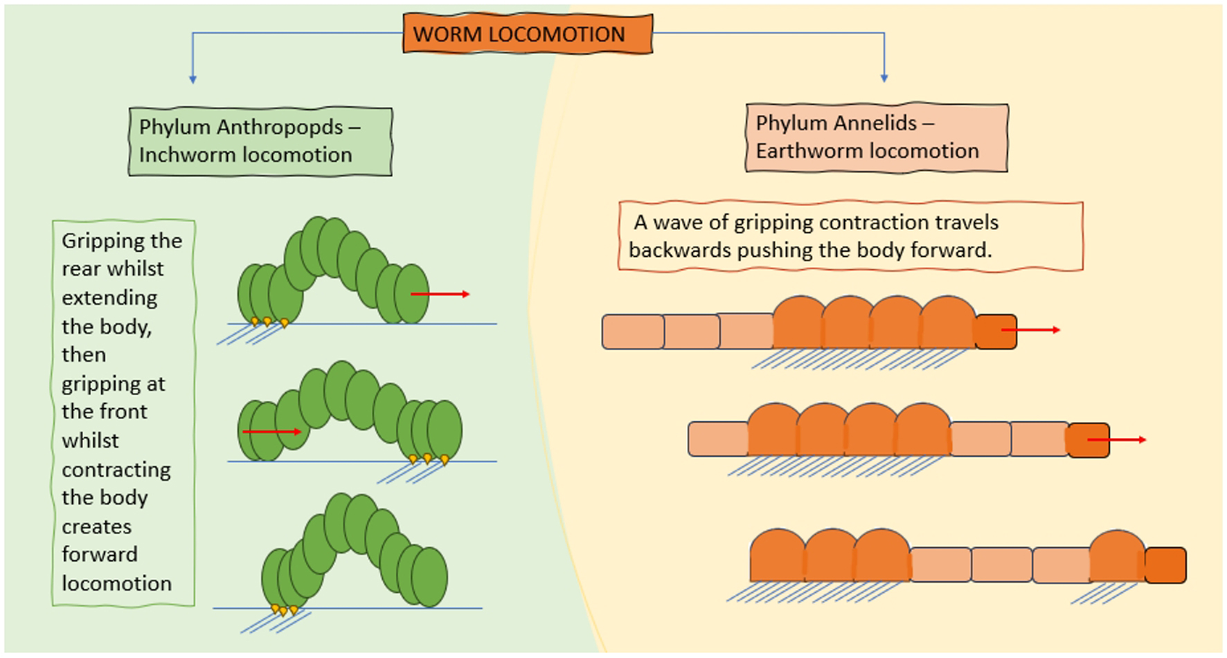
Figure 1. Demonstration of inchworm and earthworm locomotion.
Both methods of worm motion rely on patterned anchoring and extension to create propulsion. To travel up a vertical pipe, robots must apply a traction force to the pipe to prevent falling or slippage, something that lends itself naturally to worm-like robotics. Furthermore, soft actuators, which tend to be made from high-friction materials such as rubber, are a natural choice for these worm-like robots[13]. Smart materials are also often used as constituents within these devices, such as shape memory alloys and dielectric actuators, or alternatively, they may use linear solenoids that bend the structures to create a force on the pipes[13,14]. Whilst worm-like robots have been developed for other uses such as exploration[15] and gastrointestinal inspection[16,17], this review will focus on their applications within pipework.
To analyse the applicability of worm-like robots to pipe inspection, we first must define what is important for a robot to carry out pipe inspection.
1. Locomotion: The robot must be able to effectively move through pipework. For most applications, this requires that a robot can move in any orientation around swept bends and tight turns.
2. Wall-press: The robot must be able to grip the pipe walls with enough force to hold its own weight and the addition of any sensors or loads required for inspection.
3. Steering: The robot must be able to turn left or right at junctions so that entire pipe networks can be explored.
4. Navigation and mapping: Thus, any areas of damaged pipe network or contamination can be located.
This paper will first discuss fabrication, wall-press ability and motion or earthworm mechanisms and inchworm mechanisms separately as their difference in locomotive strategy affects these areas. Then, control, navigation and mapping of worm-like robots will be discussed.
EARTHWORM MECHANISMS
Fabrication
Earthworm mechanisms are robots that move using peristaltic motion. These platforms are made from a series of identical actuators which anchor when contracted axially and extend when contracted radially. They contract actuators in waves moving from the front to the back in turn, resulting in forward movement imitating that of an earthworm. A demonstration of an Earthworm mechanism in a pipe can be seen in Figure 2.
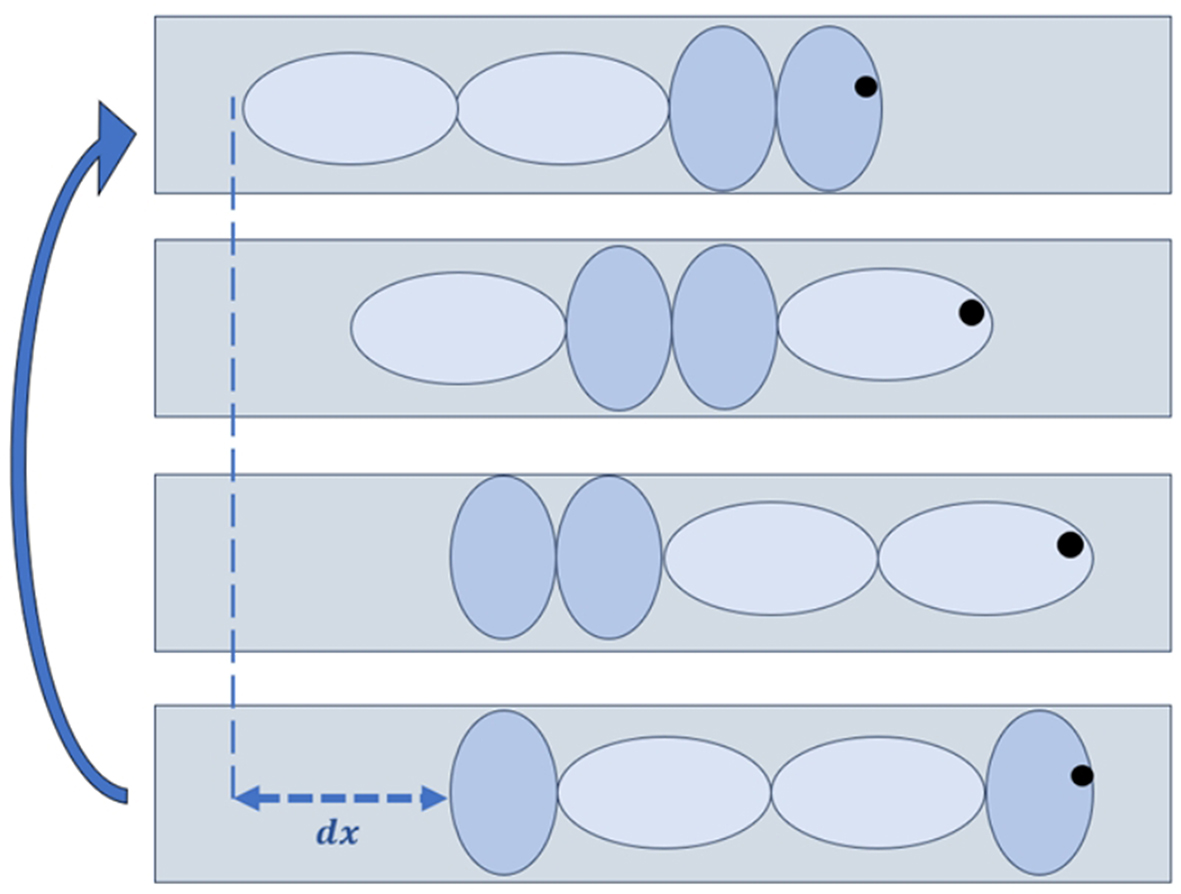
Figure 2. Diagram of an Earthworm mechanism moving through a pipe.
The advantages of a modular design such as this are that the robot’s length can be extended easily, multiple units can be gripped at once, increasing stability, and only one actuator unit needs to be designed. The units can be constructed using a variety of actuation methods; for example, Nemitz et al. used voice coils capable of creating 1 N of force to actuate a rubber muscle-like actuator[18]. These modules were connected in series. Gao et al. used shape memory alloy springs, and Das et al. developed an earthworm robot using a biomimetic actuator containing encapsulated fluid mimicking the coelomic fluid seen in earthworms[14,15] [Figure 3A]. In a study by Das et al., the actuators have three states: (a) elongation from positive pressure; (b) partially relaxed with no pressure input; and (c) radial expansion from negative pressure[15]. This is advantageous as both actuation modes (a) and (c) are active. This contrasts with most worm robots that use pneumatic actuators such as Pneumatic Artificial Muscles (PAMs) which do not exert an active force during elongation[19], making their response slower and less predictable. Ikeuchi et al. and Tanise et al. overcame this issue by reinforcing PAMs with springs to create an active force on release[20,21]. To increase the actuator response further, Tanise et al. also included a pressure-driven valve at the air connection to each of the PAMs[20]; thus, the air was released directly to the environment, decreasing the elongation time of the unit from 3.4 to 1.1 s. By reducing the elongation or contraction time, the velocity of the robot can be increased. Whilst actuator response is crucial for the speed of the robot, other factors are important to consider when designing the actuator unit. To create motion in an earthworm mechanism, a sufficient contraction length to extension length ratio is needed. The larger this is, the further the robot will travel in a single cycle of motion. Theoretically, the distance travelled in a cycle should be the number of units multiplied by the extension length of a single unit. Tang et al. developed a pneumatically driven earthworm robot made from silicone chambers[13]. The 2-unit robot should theoretically move around 10 mm per cycle (though it was found to move only 5 mm practically). This difference between expected and real movement is due to slippage. This can be reduced by increasing the grip on the surface of movement. Not only is this important to maximise movement in a single cycle but also to render movement more predictable as the position of the robot will be better known which is vital for mapping and navigation.

Figure 3. Examples of Earthworm Robots and actuators. (A) Fluid-filled pneumatic actuator under positive and negative pressure adapted with permission from Das et al.[15]; (B) CMMWorm in a 15.2 cm Ø pipe developed by Daltorio and Kandhari. Provided by Daltorio et al.[24]; (C) Earthworm robot made from pneumatic artificial muscles, reprinted with permission from Sato et al.[26]; (D) Wireless magnetically actuated Earthworm Robot reprinted with permission from You et al.[30]. CMMWorm: Compliant Modular Mesh Worm.
Mesh worms are a type of earthworm robot made from a single piece of mesh as opposed to a series of actuators. Such materials, akin to those seen in McKibben Actuators, elongate when their diameter is shortened due to the nature of their geometry. Mesh worms can use soft actuators such as Shape Memory Alloys and nickel-titanium wrapped around a mesh tube to create a smaller diameter and, hence, elongation at points along the mesh[22]. The sequence of this actuation around the mesh creates a peristaltic locomotion. Other mesh worms, such as the Compliant Modular Mesh Worm (CMMWorm)[23] presented in Figure 3B and Softworm presented in Daltorio et al., make use of traditional actuators such as servomotors which use a cable-driven mechanism to contract the mesh[24]. Softworm was actuated using 12 hoop actuators pulled by a single motor. The hoop actuator contracts sections of a helical mesh which is reinforced with longitudinal springs to return it to its initial state after contraction. Daltorio et al. model each segment as a rhombus to calculate the lengthening under actuation whilst also using a spring-mass model to determine the forces acting on the pipe[24]. The size of the motors and mesh structures mean they are more suited for medium-sized pipes (> 75 mm Ø); CMMWorm was demonstrated for use in a 152 mm Ø pipe[23].
Wall-press ability
In pipe inspection robotics, the robot’s capability to create sufficient friction with the pipe walls is called wall-press ability, which is vitally important for load carrying and vertical climbing. Ideally, a robot would be able to create enough force to carry its own weight and an additional extra load. Dai et al. developed an earthworm made from tensegrity structures that were actuated using linear solenoids which bent the structures to create a force on the pipes, with the resulting earthworm mechanism capable of traversing 155 to 195 mm pipes with a gripping force of 55 N in the 155 m pipes and 30 N in the 195 mm pipe[25]. Dai demonstrated the robot’s ability to carry an 850 g load in a 195 mm pipe. It is more common for earthworm robots to be made from pneumatic actuators such as PAMs akin to the one developed by Sato et al.[26] [Figure 3C]. Sato et al. used axially reinforced PAMs where a single unit is capable of a 300 N traction force in a 102 mm pipe[26]. The robot, by contrast, only weighed 6.3 kg, and thus, it could carry a load vertically. However, creating as much traction force in smaller pipe diameters is more difficult as friction is proportional to contact area and smaller actuators in smaller pipes will create less contact area. One way to enhance wall-press ability in smaller earthworm robots is to increase the number of units contracted at a time. However, this action can affect the robot motion by decreasing its speed.
Motion
When considering peristaltic motion in earthworm mechanisms, speed is not just a question of fast actuation but also of optimising the motion. For an Earthworm mechanism, the motion can be defined in terms of “Wavelength”, “Propagation speed” and “Number of waves” [Figure 4]. At any time within a peristaltic Earthworm mechanism cycle, some number of units will be elongated, with this number referred to as “Wavelength” (l). To move, the number of units gripping the pipe will shift back by a set number of units referred to as the “Propagation Speed” (s). Lastly, an Earthworm mechanism can have more than one group of gripping units actuated at a time, a number referred to as “Number of Waves” (n). By convention, an Earthworm motion pattern can be described by l-n-s[20,21,27]. For example, the motion pattern in Figure 4 may be described as 4-1-1.

Figure 4. Graphic explaining the terms used to define the wave motion in peristaltic motion. Here, Wavelength = 4, Propagation
We can use these values to calculate the speed of the robot. If we know the length of contraction of a single unit r, and the time each unit takes to contract t, then for N unit-long robots, the distance moved is dw. As a wave of gripping units propagates from head to tail, dw and the time taken Tw can be given by Equations (1) and (2).
We can derive the speed of the robot as:
Ikeuchi et al. found that the fastest motion sequence varied in different pipe sizes due to the contraction time differing across pipe diameters[21]. As in Equation (1), the speed of the earthworm robot can be increased by increasing the number of elongated units l, propagation speed s and number of waves n. All these values are constricted by the number of modules in the design, suggesting that, by increasing the length of an Earthworm mechanism, the speed can be increased.
Mano et al. demonstrated this experimentally by creating 4-module and 7-module earthworm mechanisms and comparing their speeds[28]. Whilst the 7-unit worm could reach a speed of 42.8 mm/s, the 4-unit module was only capable of reaching 11.6 mm/s [Figure 5]. As evidenced by Equation (3), other ways to increase the speed of earthworm robots include increasing the length of contraction or reducing the contraction time. In pneumatic robots, the modules require a pressure input into the bellows which is often controlled externally via valves connected to the modules through pneumatic tubing[13,17]. The number of modules is thus limited by the volume of tubing the design can accommodate, posing limitations on speed. However, not all designs require a large amount of tubing. Yamamoto et al. developed a peristaltic robot design that used only two air inputs regardless of length[29]. As opposed to creating a peristaltic motion through segments, the design uses a slide roller. As seen in Figure 6A, a gripping unit can be moved and activated by varying the pressure inputs from either side. Another advantage of this design is that it can move in two directions. The robot can be of any length, which is correlated with the size of the stroke from a cycle of motion. The demonstrated robot was 90 mm long and 38 mm wide and could produce speeds of 100 mm·s-1 horizontally and 40 mm·s-1 vertically.

Figure 5. Comparison of the speed from a 7-unit Earthworm mechanism (A) and a 4-unit (B). Reprinted with permission from Mano et al.[28].

Sato et al. developed a novel Compact Pneumatic Valve (CPV) controlled by rotational motion of a single motor[26]. The valve can be supplied by a single source and periodically rotates an outlet hole supplying air to a different actuator in turn, while simultaneously, an outlet valve is periodically rotated too. The CPV was used to control a 7-module earthworm In-Pipe Robot (IPR) [Figure 6B]. The placement of the inlet and outlet valves was two actuators apart, resulting in a 5-1-1 earthworm robot. This streamlines the design since an external valve system is not needed and only one tube needs to be connected to the robot, though tubing between the individual actuators is still required.
Sato et al. integrated solenoids directly into the actuators, meaning they could release air directly from the actuator to the environment and hence, only one supply line was required[26]. This was used to create a 6-unit robot capable of traversing 150 mm pipelines. Rigid valves can be quite large meaning that by integrating them directly into the robot, miniaturisation potential is limited. A wireless and tubeless earthworm mechanism [Figure 3D] is demonstrated by You et al.[30]. The robot is made from magneto-active elastomers which expand radially and contract when exposed to a magnetic field. Though the robot manages to navigate straight pipes without tethering, it does require a magnetic field to be created and moved to create actuation which is impractical in most pipe inspection environments.
Seok et al. determined the speed of a mesh-based earthworm robot using Equation (3), supposing that if all other variables were kept constant, speed would be proportional to the wavelength (l)[22]. However, experimentally, they found that the shorter wavelength motion was faster at 3.47 mm·s-1. It was observed that for longer wavelength (l), fewer units are in a gripping state, so less friction is being created which can result in slippage. Equation (3) may be considered an accurate calculation of speed for the robot if the number of units gripping at a moment is enough to keep the robot stable. Hence, it may be argued that the speed of a robot may be most adjustable if the gripping force of a single unit is sufficient to prevent slippage. This is particularly difficult in robots made from mesh material as their lattice-like structure does not create significant contact area with the pipe when actuated, and they tend to be made of low-friction materials such as nylon[23] further reducing their wall grip ability.
Many worm-like pipe robots do not have any active bending actuation facility. These platforms rely on their compliance and the constraints of the pipe environment to guide their movement. However, this can only work in pipe structures that do not contain complex junctions such as Y and T-bends where the robot is required to actively steer itself. To create active steering in the robot, soft bending actuators need to be integrated into the design. Soft bending actuators are made from a variety of materials ranging from elastomers[31] to electroactive polymers[32] and shape memory alloys[33]. Their actuation can be driven by pressurised fluids, electric stimuli, or even chemical reactions. Pneumatic bending actuators tend to be the most popular in worm robots due to their low cost and high power-to-weight ratio.
As earthworm robots tend to be modular or are made from a single piece of material, it is difficult to integrate steering into the modular design without adding a separate steering unit. Omori et al. designed a pipe inspection earthworm robot made from two plates connected by flexible belts[34]. Two motor crank systems inside the units were used to extend and contract the motor creating expansion and elongation.
To create steering, one side of the robot is extended more than the other [Figure 7], creating a planar turning motion. While the active turning method was not practically tested in a pipe environment, the robot was capable of navigating bends of up to 90 degrees by using forward peristaltic motion alone. Multiple actuators were required for a single unit to enable steering. This design makes miniaturisation difficult; consequently, the robot had a contracted width of 82.7 mm. In pneumatic earthworm mechanisms, steering may be integrated by splitting the units into chambers to create a force imbalance. Tang et al. also developed an earthworm robot with turning capabilities built into the modules by fabricating a single earthworm unit from three pneumatic chambers[13]. Three modules were used to create a full robot, and when contracted, the Tang et al. platform had a diameter of 32 mm[13]. However, when placed vertically, each module could only produce a bending angle of 7-9° which could affect its suitability in pipe networks with sharp turns.

Figure 7. Diagram of the turning mechanism used in the study of Omori et al.[34].
The integration of full body steering into the actuation units of an earthworm robot may not always be required. Zhang et al. demonstrated that a mobile pipe robot can successfully traverse multiple bends, including vertical T-junctions, using a steering mechanism at the head of the robot[35]. Hence, if there is enough driving force from the robot body, steering at the head may be sufficient. This was demonstrated by Liu et al. who added a soft bending unit onto the top of a modular inchworm robot[36]. The robot was then able to navigate more complex junctions such as Y-junctions.
INCHWORM ROBOTS
Fabrication
Inchworm robots are defined by having two gripping units on either side of a central extension unit, though they may also have a separate bending unit or have bending integrated into the extension unit. These robots may be connected in series to make such a modular device resemble an earthworm robot[11]. The units can be connected by rigid parts or the whole robot can be made from flexible material. Bertetto and Ruggiu created one of the first inchworm robots for pipe inspection in 2001[37]. Here, the gripping units were constructed from expanding pneumatic bladders whilst the extension unit was made from a stiffening actuator which shrunk when pressure was applied. Modern inchworm robots use similar actuators to those presented in this early paper, with expanding pneumatic bladders being one of the most common types of gripping units still seen in recent inchworm robots. The materials used to create the actuators are vital in terms of creating robust and reliable gripping and propulsion units that can be characterised and controlled. Design considerations for soft actuators are made to control the behaviour of the actuator when supplied with an air input or vacuum, where fabric sleeves[21], fibre reinforcements[27,28], carbon fibre reinforcement[38], and the shape of the actuator[10,26,29] can all be used to restrict and direct the motion.
Basem and Bastaki made an inchworm robot with micro-DC motors alongside several compliant structures that bent to create a desirable force or motion[39] [Figure 8A]. The clamping unit was made from metal sheets that bent with motor-driven linear contraction. Further, the central module was developed to drive and steer the robot and was made from three nylon rods that could be extended or shortened to create turning or movement. The robot demonstrated its ability to move through 100 mm diameter pipes with 90-degree elbow turns.

Figure 8. (A) Inchworm mechanism made using traditional rigid actuators. Reprinted with permission from Basem and Bastaki[39]; (B) Comparison of the initial gripping unit developed by Kusunose et al.[40]. (i) The improved mechanism integrated into the whole robot by Hayashi et al.[41], (ii) Both images printed with permission from Hayashi et al.[41]; and (C) Inchworm robot developed by Li et al. reprinted with permission[44].
Wall-press ability
Kusunose et al. created a gripping unit made from a silicone tube covered in a ruffled fabric sleeve that was connected end to end to create a circular shape[40] [Figure 8B(i)]. The fabric sleeve constrained it to expand radially while silicone tape was added to the actuator to create more grip. This unit could hold a force of around 40 N when supplied with a pressure of 300 kPa, a figure which was later improved to a holding force of 160 N at 100 kPa when the gripping unit was redesigned as an O-shaped rubber tube that inflated to grip the pipe as seen in Figure 8B(ii)[41]. The difference between the two actuators had to do with the contact area between the actuator and the pipe as frictional force Ff is directly proportional to surface area A. Rubber is capable of deforming into the cavities of hard surfaces to create a large contact area, and thus it is ideal for such actuators[42]. Hence, one of the most common gripping units seen in pneumatic inchworm robots is radially expanding bellows of air made from elastomer[17,37,40,41]. The contact area is an important part of designing an inchworm robot as it determines how much load can be carried and hence if the robot will be capable of carrying sensors/tools required for inspection. The gripping unit in the study by Fang et al. was placed between two rigid plates limiting the contact length to the displacement between the plates[43] [Figure 9]. They[43] determined the relationship in Equation (4) between the maximum load Fmax given pressure p, the pipe diameter Dp, and the minimum contact length Ls.
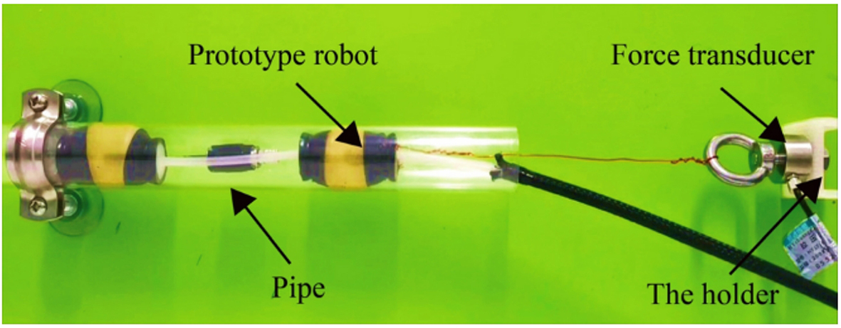
Figure 9. Image of the robot produced by Fang et al. being tested for force analysis. Reprinted with permission from Fang et al.[43].
Fang et al. found that for a 25 mm diameter pipe, the gripping units would be sufficient with a 32 mm contact length, whereas for a 40 mm pipe, a 24 mm contact length was sufficient[43]. The robot was demonstrated in vertical and U-bend pipes of 90 mm diameter. Generally, a smaller gripping length allows a robot to navigate a turn more easily. In the case of robots where the contact length of gripping units is set between rigid plates, this may limit whether the robot can approach a bend or create a limit on minimum pipe diameter. If a gripping unit expands longitudinally and axially, then the contact length when it is not inflated is less of a burden. For less constrained actuators, more mechanical analysis may be used to determine the contact length under expansion and, hence, confirm whether the gripping force is sufficient.
Li et al. created an inchworm robot with ellipsoid-shaped gripping actuators capable of extending both radially and axially[44] [Figure 8C]. To determine the contact area, Li et al. used strain relationships at the contact boundary[44]. The strain on a thin-walled pressure vessel can be given by latitudinal (σ1) and longitudinal (σ2) stress, as given in Equations (5) and (6).
Where p is the gauge pressure, r the radius of a thin-walled cylinder resembling that shown in Figure 10, and δ the thickness[45]. If we consider a pipe wall of diameter d with an expanded balloon in it, we can calculate the latitudinal strain at the boundaries of where the balloon contacts the pipe under expansion xb and -xb. Using the stress-strain relationship, we can also derive Equation (7):

Figure 10. Diagram of longitudinal and latitudinal stress on a thin-walled cylinder.
Where E is the elastic modulus and ε the expansion which can be expressed in terms of ε = d/y (xb) where
Not all inchworm robots are actuated using pneumatics; examples of other softworm in-pipe robots actuated through other means have been researched. Tang et al. developed an inchworm robot capable of inspecting 9.8 mm Ø pipes using Dielectric Actuators (DEAs) to create propulsion units and an anchoring unit made from smart composite microstructures[46]. DEAs are electroactive polymers that deform through the induction of an electric field. They created the elongation unit from a single DEA, whereas the anchoring unit [Figure 11], was made from a DEA between a mechanism whose diameter decreases when the DEA itself elongates[46]. The Youngs modulus of the DEA in the elongation unit was much lower than that in the anchoring unit (100 kPa at 100% strain compared to 420 kPa). This ensured that the anchoring unit had a stronger energy transfer for a smaller movement creating more force on the mechanism. Tang
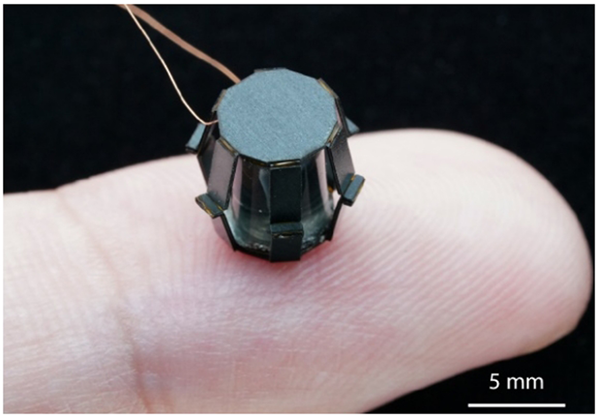
Figure 11. Millimetre scale gripping unit that uses Dielectric Actuation reprinted from Tang et al.[46] with permission.
Calculating the optimised activation voltage or pressure to use in the actuators is vital in order to know that the robot is secure during elongation/contraction and to ensure that the robot produces a suitable elongation. Liu et al. created a modular worm-inspired soft robot using radial expansion, elongation, and spatial bending pneumatic actuators[36] [Figure 12A]. Here, a Magnetostrictive Displacement Sensor (MDS) was used to measure the deformation of the axially expanding pneumatic actuator, thus demonstrating that the elongation of the actuator was linear for deformations < 60 kPa[36]. Radially Expanding Pneumatic Actuators (REPAs) used force sensors to gauge when sufficient grip is present to achieve the target goal. At 250 kPa, the robot has enough grip to hold a load of 240 N more than the weight of the robot, meaning it can move vertically against gravity. The inchworm robot demonstrated its ability to move through straight pipes and U-bends at a variety of inclines.
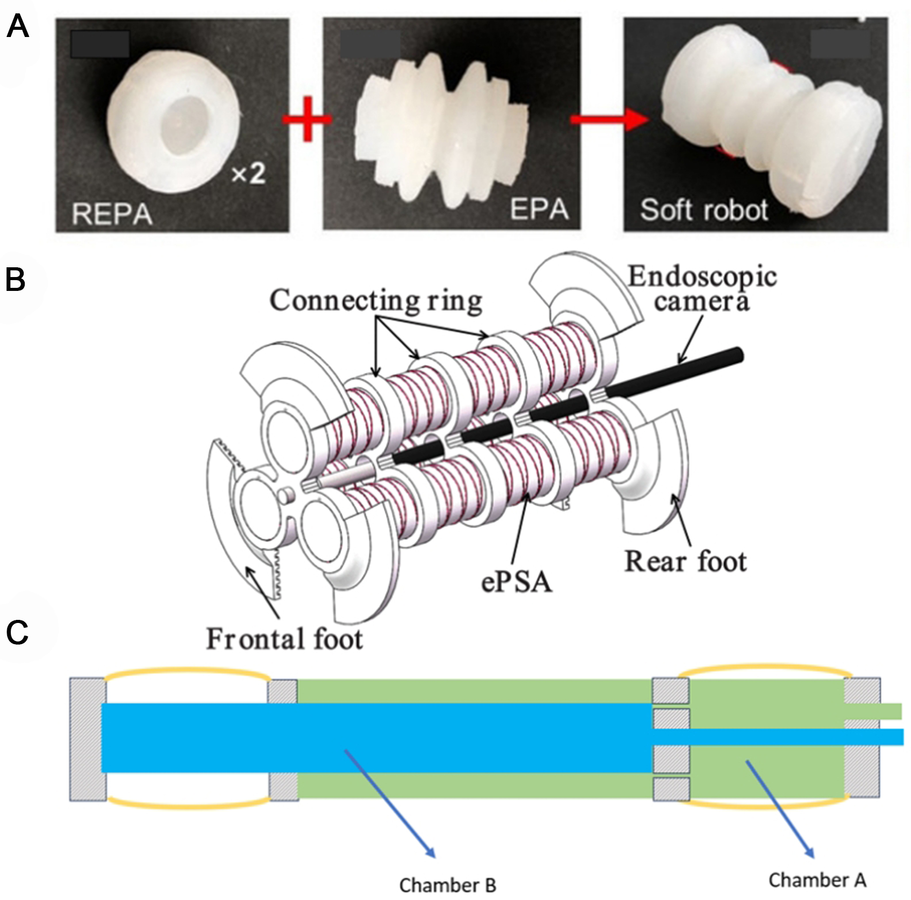
Figure 12. (A) Soft inchworm robot developed by Liu et al.[36], reprinted with permission; (B) Soft inchworm robot made from three eSPAs and two flexible feet. Reprinted with permission from Zhang et al.[55]; (C) Internal structure of duplex chamber inchworm mechanism based on that presented in the study of Yamamoto et al.[58]. REPA: Radially Expanding Pneumatic Actuator; EPA: Expanding Pneumatic Actuator; eSPAs: Extensible Pneumatic Soft Actuators.
Motion
Similar to an earthworm mechanism, the amount of movement produced in a cycle depends on the extension that can be created by an actuator. Producing a large determinable amount of contraction is desirable to increase movement and speed and make the behaviour of the robot more predictable. Within a typical inchworm mechanism, the extension unit typically consists of one or more pneumatic actuators. Extension units should create a driving force capable of lifting the body’s full weight and any friction from the pipe, whilst creating a reasonable displacement. Extension units can range from elastic bladders covered in sleeves to prevent radial expansion to creased pneumatic bellows[44], unfolding/origami actuators[47,48], vacuum-actuated buckling mechanisms[49,50], traditional rigid linear actuators, and smart materials. The structural considerations ensure the expanding behaviour of the bellows is more predictable and constrained to the axial direction.
PAMs with folds or pleats can be modelled using geometric force models[51,52], whereas other methods include biomimetic models that model pneumatic actuators akin to muscles[53,54] and force-spring models[55-57]. Zhang et al. created a robot consisting of three parallel PAMs (modelled biomimetically as muscles) and two flexible feet[55]. Unlike force-spring models, biomimetic models also consider the force axially that causes the pneumatic actuator to expand radially. The relatively simple robot [Figure 12B] presented by Zhang et al. has gripping units which do not require inflation, and thus, it can reach speeds of 18.7 mm·s-1 forwards and 17.7 mm·s-1 backwards[55].
Pneumatically inflated robots face the same difficulties as earthworm ones, where miniaturisation and high speeds can be difficult to achieve when there are a lot of air supplies to consider. Usually, an inchworm mechanism will feature at least three inputs to control each unit. Yamamoto et al. reduced this by creating such a robot made from two chambers[58] [Figure 12C]. The two chambers can be used to inflate corresponding grippers at low pressures and both the corresponding gripper and the elongation units at high pressures. By switching between high and low pressures in each chamber, the robot can achieve inchworm locomotion. It can produce speeds of 45.5 mm·s-1 in horizontal and 23.7 mm·s-1 in vertical 25 mm pipes, albeit not as fast as the robot presented in Yamamoto et al. though within a significantly smaller diameter[29].
Lim et al. managed to produce an inchworm robot using one pneumatic line with the rear gripping unit, elongation unit and front gripping units separated by holes of different sizes[59]. Each hole required a threshold pressure for the air to pass through; hence, the inflation of each chamber travels from rear to front with the deflation from rear to front the same [Figure 13]. This creates the desired peristaltic motion where higher pressure leads to less time required for a cycle of motion.

Figure 13. Inflation sequence of a passive valve inchworm mechanism, similar to that seen by Lim et al.[59].
The robot developed by Lim et al. can achieve high-speed motion reaching 50 mm·s-1 attained in a 16 mm pipe, which is significantly smaller than the pipes used in the study of Yamamoto et al. although unlike this robot it can only perform one directional motion[58]. Gilbertson et al. made an inchworm robot driven by hydraulics, similar to the study of Lim et al.[59,60]; the robot is driven using only one supply line; however, in this case, the supply is water. Gilbertson et al. use passive valves that release water into the next chamber when a certain pressure threshold is reached managing a speed of 13.5 mm·s-1[60].
From Table 1, the conclusion can be drawn that the speed at which the actuation method can be delivered to the robot influences the overall speed of the robot. Fluid-driven robots can increase speed by introducing passive valves, reducing tubing, and removing the reliance on solenoid valves. This means that the fluid must travel less distance to pressurise or depressurise the actuators, reducing the overall time required to complete a sequence of movement. Passive designs may increase the speed of an inchworm robot but control over the individual chambers is lost. If more gripping power was required in an inchworm mechanism where the two gripping chambers were actuated by separate supply lines, the pressure in these chambers could be increased simply by increasing the inflation time. However, in a passive design, the entire mechanism would need to be redesigned. This leads on to a larger implication that the robot may be less adaptable to its environment. Even if sensing were included, the robot would not be able to change its motion when required due to the over simplicity of its design. Hence, it is difficult to design a stable high-speed fluid-driven inchworm robot for small-diameter pipe navigation. To overcome this imbalance between speed and stability, one solution may be to use a different method of actuation altogether. Tang
Examples of high-speed inchworm robots
| Robot | Actuation connection | Pipe diameter | Speed (Horizontal) |
| Zhang et al.[55] | 3 pneumatic tubes | 46 mm | 18.7 mm·s-1 |
| Tang et al.[46] | Electrical (wiring) | 9.8 mm | 55.93 mm.s-1 |
| Yamamato et al.[58] | 2 pneumatic tubes | 25 mm | 45.5 mm·s-1 |
| Lim et al.[59] | 1 pneumatic tube | 16 mm | 50 mm·s-1 |
| Gilbertson et al.[60] | 1 hydraulic tube | 19 mm | 13.5 mm·s-1 |
This suggests that electrical actuation of soft materials may be required to push the boundaries of speed and size reduction in worm-like pipe robotics. Soft electric actuation methods are difficult and expensive to fabricate which may be why there are only a few examples of their use in pipe inspection worm robots.
Many pipe networks contain junctions where the robot may be required to steer. To steer in a desired direction at junctions, the inchworm robots must bend. To cause bending, the soft actuator must create an unbalanced force under inflation through methods such as fibre reinforcement[31], asymmetric design[61], or the addition of fins (as seen in the popular PnueNets actuator[62]). Hwang et al. showed that in ballooning actuators, the addition of fins creates a more linear response of the bending angle to input pressure, a characteristic that is desirable for controllability[63]. Xavier et al. analysed fluid-driven actuators specifically for their use in inchworm robots[64]. They found that for bending, a semi-circular ballooning actuator reaches a higher bending angle fastest and that fibre reinforcement made little difference. Xavier et al. subsequently developed a worm-like robot using soft pneumatic actuators[64]. A semi-circular ballooning actuator was placed at the tip to guide the robot around corners. However, this bending only appears to occur in one dimension.
Creating bending actuation in three dimensions can be executed by placing multiple linear actuators of varying lengths around a central axis. This method is commonly seen in continuum robotics but can also be used in worm-like soft robots. Zhang et al. used a worm-like robot with a bending and extending actuator in the middle[65]. It was composed of three chambers, where creating a difference between the pressures in each chamber would cause bending [Figure 14]. Pressure values for different bending angles were found experimentally, and the robot was demonstrated to actively turn around 45-degree junctions. The middle unit used in the research of Zhang et al. is referred to as a Parallel Bellows Actuator (PBA) and is a popular design in soft robotics[65]. The PBA consists of three soft actuators placed in a triangle configuration around a central axis. The kinematics of such an actuator can be modelled using a constant curvature assumption. The constant curvature model says that the tangent angle to the imaginary backbone of the actuator is a constant. Whereas, in their study[65], the bending unit is part of the extension unit. In some inchworms, the turning mechanism is placed at the head of the robot, and the rest of the robot is guided by its movement. To improve the robot’s agility, Liu et al. added a steering module containing a REPA and a Soft Bending Pneumatic Actuator (SBPA)[36]. The SBPA uses three chambers placed symmetrically around the axis allowing it to bend in any direction in space. The addition of more modules is desirable as it can increase the speed and stability of the robot, as gaps in the pipes and obstacles are more easily avoided.
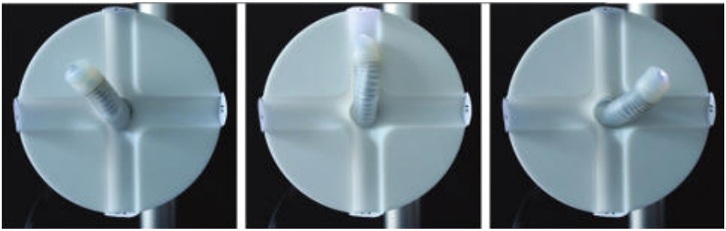
Figure 14. Example of three-chamber (PBA) inchworm robot turning its head in multiple directions. Reprinted with permission from Zhang et al.[65]. PBA: Parallel Bellows Actuator.
Especially in the case of a T junction, the robot cannot rely on the guidance of the pipe walls for direction. To ensure successful operation, it should be able to assess the desired position of its end effector or gripping unit and use this to calculate the actuation inputs for its bending mechanism.
Zhang et al. developed a kinematic model for an inchworm robot with a parallel actuator and two “feet” based on the following assumptions[55]:
(1) The robot features constant curvature.
(2) The gripping actuators are stationary during inflation and deflation.
(3) The inflating parallel actuators keep a constant radius under inflation.
(4) The robot can be assumed to have no load or be affected by gravity.
From these assumptions and using the forward kinematics relationships defined in Webster and Jones[66], Zhang et al. can map the lengths of a 3-bellow actuator to configuration space variables (curvature) and hence task space (the end position)[67]. A static model of actuator variables (pressure in this case) can be used to calculate the required actuator inputs. Zhang et al. can predict the position of the robot gripping units after extension and then again after contraction by using this model and hence map the trajectory of the robot[55]. This trajectory plan is tried and tested in this work for an L bend where computations calculate the fastest trajectory. The robot does manage to navigate the L bend, but the trajectory is not the same as expected due to inconsistencies between the pipe conditions in simulation and real life.
As demonstrated in Table 2, the robots with the best turning capabilities all use three bellows actuators and are pneumatically actuated. There are no obvious advantages between integrating turning actuation into an inchworm propulsion unit or placing it at the head of the robot, but this may be due to a lack of examples. There are few examples of worm robots that can navigate two-directional junctions, and though some of the robots are able to turn L-junctions, there are also many examples of worm-like robots without active turning also being able to achieve this by simply relying on compliance alone. Moreover, there is yet to be a robot that demonstrates autonomous sensing to guide turning.
Comparison of bending abilities in worm-like pipe robots and demonstrated ability
| Robot | Bending method | Actuation | Angles | Demonstrated ability in pipes |
| Integrated inchworm[50] | Three vacuum actuators | Pneumatic | 40 | Navigation of straight pipes |
| Earthworm[13] | Three pneumatic chambers are arranged axially | Pneumatic | 7-9 degrees per segment | Navigation of straight pipes |
| Inchworm with bending actuator at the top[64] | Semi-circular bending actuator | Hydraulic (Safe in medical applications) | 90 degrees Also presented a PBA that could do 85 | Navigation of straight pipes and two unconnected planar tubes placed at 90 degrees to each other |
| Earthworm[34] | Length control from servo | Electric, motor driven | n/a | Navigation of straight pipes and L Bends |
| Inchworm Integrated[55] | Parallel Bellows Actuator | Pneumatic | Not recorded | Navigation of straight pipes and L Bends using trajectory planning |
| Inchworm with bending actuator at the top[36] | Three pneumatic chambers | Pneumatic | 25 | Navigation of straight pipes, pipes with gaps, pipes of variable diameter and Y junctions |
| Inchworm Integrated[65] | PBA | Pneumatic | 120 degrees (two actuated chambers) 90 for one | Navigation of straight pipes and a pipe with multiple branches, but no evidence of a 90-degree sharp turn |
COMPARISON OF MECHANISMS
As shown in Figure 15, there is much similarity between the capabilities of Earthworm and Inchworm mechanisms. Earthworm mechanisms offer a solution for small-diameter pipe inspection for straight and bent pipelines in any orientation with little complexity. They have demonstrated a variety of speeds and an ability to travel in two directions. Their relatively simple design makes them easy and cheap to fabricate and control, as more than one unit can be actuated at a time. Moreover, sensors such as cameras could easily be added to the head of the robot to aid inspection purposes. These could be used to identify typical distress indicators required in pipe inspection[68]. These devices could further be used to inspect underground gas pipes which are currently inspected using manually operated instrumentation such as ground penetrating radar inspection and walkover beacon systems[69]. Earthworm robots offer a remote semi-autonomous cheap alternative to this manual method. Without steering, straight pipe mapping is relatively simple for a tethered robot as the distance travelled can be indicated by the length of the tether. Alternatively, a visual SLAM algorithm could be used on the camera head. The use of earthworm mechanisms in more complex pipe networks is limited by difficulties in steering, as the units are optimised for both contraction and extension; thus, steering is difficult to work into the design. Inchworm robots demonstrate a similar ability to traverse small-diameter straight pipes vertically and horizontally. However, unlike earthworm robots, they have the advantage of superior turning ability as the extension unit in an earthworm can be created in the form of a three-bellow actuator. Nevertheless, there are only a few examples of inchworm robots navigating pipe networks with sharp turns, and it is unclear in these experiments whether the steering motion is precalculated given knowledge of the setup or preprogrammed for a known environment. Both mechanisms rely on the control of expanding or contracting soft actuators in sequence. Though the motion sequence differs, the control strategies can be considered similar enough to discuss together.

Figure 15. Comparison between Earthworm Mechanism and Inchworm.
CONTROL AND NAVIGATION
Control and shape sensing
Worm-like robots mimic the peristaltic motion seen in worms in nature by triggering actuators in a sequence. In pneumatic worm robots, this is usually done using external solenoid valves which release and input a constant pressure for a set amount of time to each actuator in sequence[36,41,47,49,50]; an example of this on/off control method can be seen in Figure 16. This has also been shown to be done using onboard pneumatics[37]. The same method can be applied to electrically actuated robots with set voltages being supplied to soft actuators in sequence[46]. The phase cycles for each actuator are key to the speed and efficiency of the robotic platform.
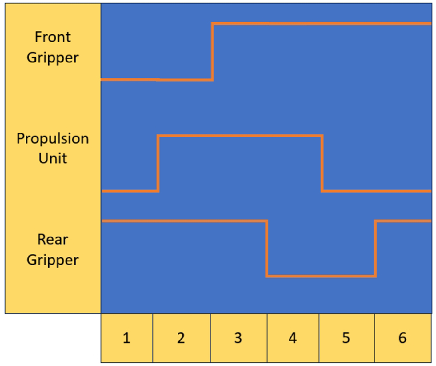
Figure 16. Example of on/off control for an inchworm robot. For a three-actuator robot, a cycle of motion can be achieved in 6 steps.
Zhang et al. used a Central Pattern Generator (CPG) to fine-tune the motion of their robot[67]. CPGs are based on behaviour seen in nature where animals can create rhythmic actions without input[70]. The CPG network connects all the valves into a central network where each one, i, is controlled by a trajectory function fi (r) where r = 2πδ where δ is the oscillator frequency. For valve control, fi (r) is a square wave where phase shifts for each actuator control the sequence of actuation and varying pulse widths control the amount of inflation. An example of a CPG network is shown in Figure 17.
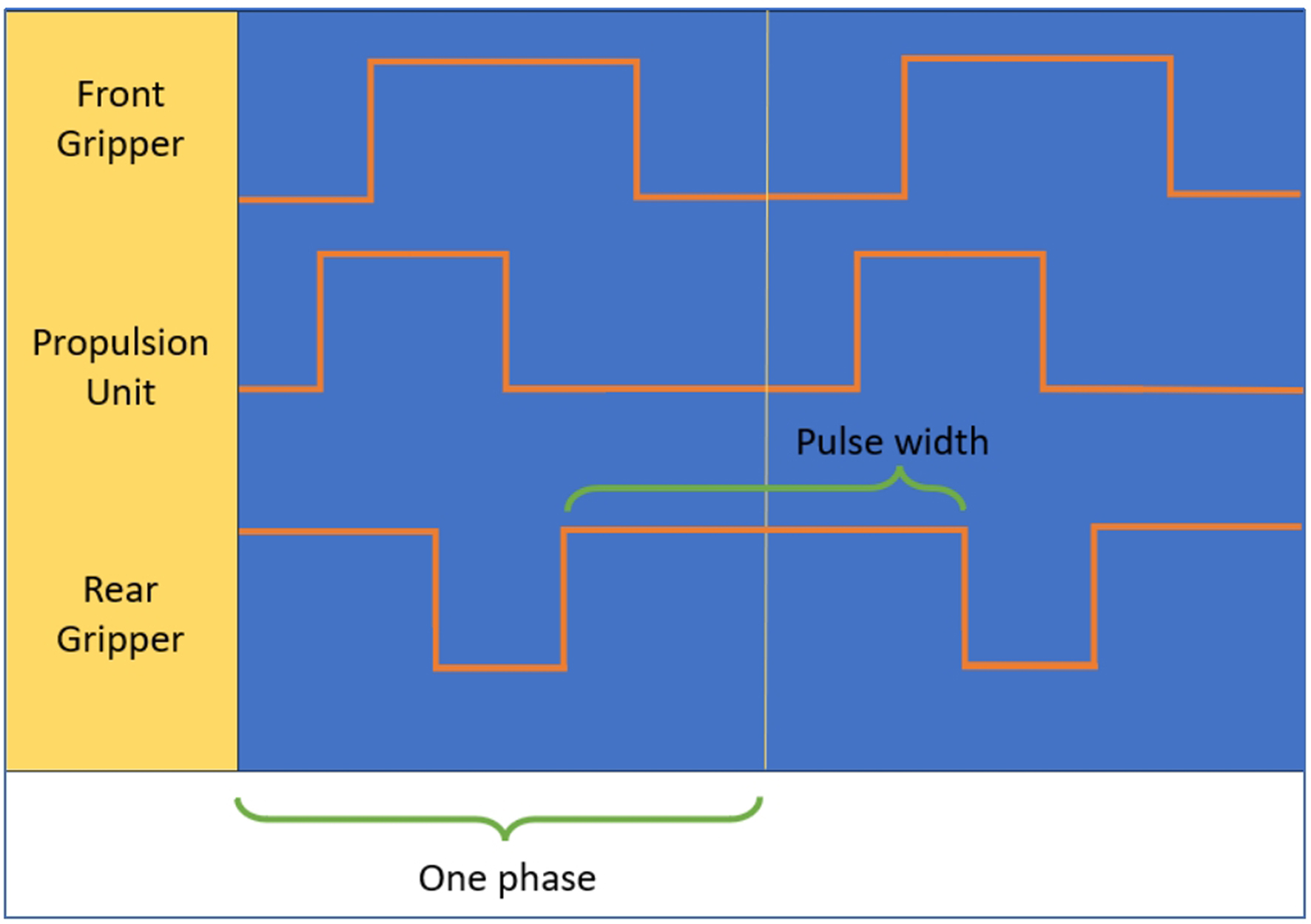
Figure 17. An example of inchworm actuation using a CPG network. CPG: Central Pattern Generator.
The advantages of CPG networks include ease of ability to change inflation times, phase shifts, and frequencies. Not only does this mean the user can easily adjust the travel speed but also turning can be implemented. Zhang et al. created an inchworm robot with a 3-actuator turning mechanism in the middle[67]. By varying the pulse width of the actuators in the CPG network, the length of the three actuators varies creating a turning motion. This was demonstrated in a 90-degree swept pipe bend. Pneumatic robots that use passive valves or single actuator movement have smaller motion cycles and, hence, simpler control systems. Zhang et al. reduced the cycle of the robot by using flexible “feet” as the gripping units[67]. Some of the feet grip the pipe while the propulsion unit moves the others. This results in a 2-step cycle of movement that increases the robot's speed to 15 mm·s-1. Other single actuation soft IPIRs use a similar 2-step cycle[71]. Though simpler to control, these systems pay little attention to gripping force and stability, making them less suitable to carry the loads that may be required for inspection.
Earthworms exhibit rhythmic behaviour similar to that made via the open loop systems discussed above, although they use stretch stimuli to achieve this[72]. Whilst open loop control is generally shown to be reliable, most experiments utilise dry uniform pipes and do not account for slips or obstacles expected in real-world applications. To improve the robustness of the robot, feedback can be used to create closed-loop solutions that can account for such occurrences. Kandhari et al. developed a cable-driven mesh worm with the cables pulling and causing the segments to expand, with slackness occurring on contact with the wall[73]. Kandhari et al. detected this by analysing load data from the cables and identifying peaks with a median filter[73]. This work was further developed by Kandhari et al. who added 36 force sensors to the robot and developed a closed-loop control system where the robot could estimate its shape and environment during movement[74]. The robot expansion was controlled by a desired force setpoint, whilst the contraction was controlled by stretch sensors. This resulted in the prevention of high-force interaction and reduced forward slip improving the motion. Calderón et al. created two robots: the first being a basic pneumatic inchworm robot and the second the same except for Stretchable Liquid Circuits (SLCs) integrated into the gripping units[75]. These extra features provided strain sensing, meaning they could determine when enough force was being applied to the pipe walls. The control system for the robots can be seen in Figure 18.
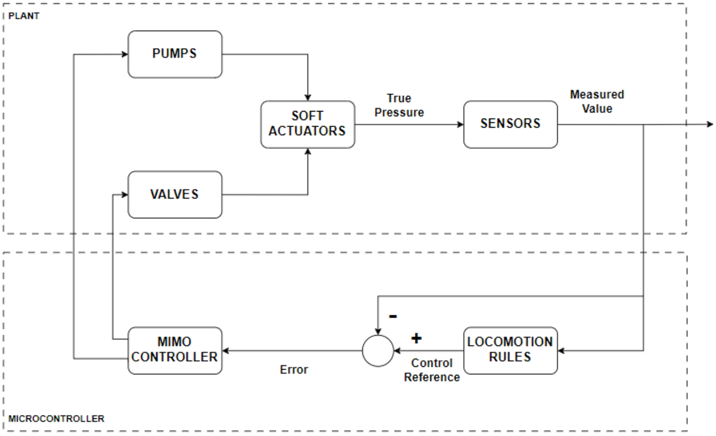
Figure 18. Flow chart demonstrating the control system used in the study of Calderón et al.[75].
The Multiple Input Multiple Output (MIMO) controller uses the same sequential on-off locomotion rules observed in other inchworm mechanisms. In the first robot without integrated strain sensors, the actuators are expanded/deflated until a set pressure is reached using PID control, whereupon, locomotion rules determine the next action. In the second robot, a setpoint pressure is still used to guide the PID inflation of the actuators, although readings from the strain sensor are used to monitor whether the robot has made contact with the pipe surface. Calderon et al. found that when the gripping actuators are expanding without external compression from the pipe wall, the resistance of the SLCs increases linearly, whereas, once under compression, the behaviour is non-linear[75]. Therefore, the actuator can be said to have made contact with the pipe wall when the change in voltage with time no longer approximates to a constant. In the second robot controller, the voltage from the sensors is used to indicate pipe wall contact. If detected, the pressure supply to the actuator is stopped and the setpoint pressure is updated to the current value. Adaptive control systems such as this allow robots to move through less predictable environments. Calderon et al. used this control system to efficiently move the second robot through a pipeline of changing diameter[75].
As demonstrated by Zhang et al., the constant curvature model can be used to model how an inchworm robot may approach a T or Y junction, although better sensing would be required for this to be considered robust[55]. The robot should be able to
(a) Identify its desired position in task space.
(b) Control its movement towards the goal position.
To achieve (a), the robot would be required to detect a junction and determine the relative position of the junction relative to its body so that it can move in that direction, something that could be done using machine vision or other environmental sensors[76]. To tackle (b), live sensing of movement is required. Goldoni et al. made stretchable nanocomposite sensors that could be integrated into robot design[77]. These were demonstrated to provide identifiable readings for bending, interaction with obstacles and stretching. To facilitate this, a pair of sensors are placed on either side of each other on the soft actuator [Figure 19], with the readings compared to infer the state of the actuator. This works well for a planar robot; possibly, similar methods could be used for 3D movement.
Figure 19. Reprinted with permission from Goldoni et al.[77]. Copyright 2024 American Chemical Society.
Navigation
Sensing of the environment is vital for the facilitation of movement control, mapping and navigation. Pipe inspection robots are most effective when robots can autonomously or semi-autonomously navigate pipework whilst feeding back information about conditions[78]. To do this, the position of faults or hazards must be determined, usually with Serial Localisation and Mapping (SLAM)[76]. Currently, a few worm robots have successfully demonstrated SLAM. Ishikawa et al. developed an odometry method to help determine the shape of the pipe the robot was travelling through[79]. A sensing unit was placed at the tail of an earthworm mechanism that consisted of two accelerometers placed on either side of a passive joint. The passive joint has a potentiometer at the joint to indicate when the robot is passing through a turn. The posture angle can be calculated by comparing the two accelerometer readings, and hence, the angle of the pipe turns determined. The robot also had a distance measurement unit that was placed at the entrance to the pipe which used an encoder to measure the length of cable (attached to the robot) that had travelled in the pipe. These measurements were used to build a 3D estimation of the pipe the robot had travelled through. The distance was measured with an uncertainty of 2.6%, whilst the angles of the pipe structure were measured with uncertainties of up to 50% when the direction of turning was parallel to the direction of gravity. The angles of measurement perpendicular to gravity were smaller due to the slack of the cable causing disturbances on the accelerometer when the robot was travelling downwards.
Improvements and advancements in worm robot mapping are required to enhance their applicability to real pipe inspection although many robots have been demonstrated with cameras at their heads[24]. Image processing could be used to create a global SLAM algorithm using landmark recognition[80], though as pipe environments are quite uniform in appearance, local information from IMU sensors and ultrasonic sensors may be needed to improve positional estimations[81]. Although, in some respects, pipe environments make visual SLAM difficult, the uniform geometry of the pipes can aid odometry. Zhang et al. showed that as feature detection is performed in a cylindrical environment of known diameter, it is relatively simple to calculate the distance moved between frames[82]. Worm-like robots tend to explore smaller pipelines
CONCLUSION AND OUTLOOK
Recently, the application of worm-like robots for pipe inspection has seen significant development. Currently, there exist many worm-like robots capable of traversing small-diameter pipes both vertically and horizontally and around tight bends. Many have also presented their ability to carry a small load such as a camera, raising the possibility of using them for inspection. However, the robots presented in this work have not been demonstrated in realistic pipe set-ups and have not been shown to exhibit specific capabilities that may be required to carry out inspection tasks. To be specific, the pipe set-ups that the robots have been tested upon are, in most cases, plastic pipes, whereas the pipes used in the industry tend to be made from a metal such as steel. Steel may pose a problem for worm robots as they present a more frictional surface, and worm robots rely on pushing their body along the pipe environment. Moreover, autonomous navigation and mapping of complex pipework has also not been demonstrated, likely due to two areas of difficulty. The first of these is the turning in a soft robot. The controlled curvature of soft actuators and robots is a complex control problem, and the pipe environment provides both guidance (in the case of swept bends) and obstruction (in the case of junctions such as T-junctions). Hence, a control system that can effectively predict the robot state and sense the robot’s environment is required. Worm robots have demonstrated their ability to turn, although a control method that could be considered robust enough for real pipe environments remains an open challenge. The other area of difficulty comes with mapping the pipe environment. Though this has been demonstrated in several non-worm-like pipe robots, there are few examples in worm robots. This is likely as estimations of robot shape and movement are required to create effective mapping algorithms and as worm robots are generally made from soft actuators this presents a significant difficulty. On top of these difficulties, there are also the problems associated with attaching sensors to small compliant robots. For the pipe inspection capabilities of worm-like robots to be realised, demonstrations of worm-like robots with more sophisticated sensing and inspection abilities are required.
DECLARATIONS
Authors’ contributions
Made substantial contributions to conception and design of study, found and analysed the relevant literature for interpretation: Blewitt G
Provided administrative and material support as well as assisting in editing of the paper: Monk S, Andrew J, Cheneler D
Availability of data and materials
Not applicable.
Financial support and sponsorship
This research was funded by the Engineering and Physical Sciences Research Council UK and Dounreay Restoration Site Ltd.
Conflicts of interests
All authors declared that there are no conflicts of interest.
Ethical approval and consent to participate
Not applicable.
Consent for publication
Not applicable.
Copyright
© The Author(s) 2024.
REFERENCES
1. Verma A, Kaiwart A, Dhar Dubey N, Naseer F, Pradhan S. A review on various types of in-pipe inspection robot. Mater Today Proc 2022;50:1425-34.
2. Mishra D, Agrawal KK, Abbas A, Srivastava R, Yadav RS. PIG [Pipe Inspection Gauge]: an artificial dustman for cross country pipelines. Procedia Comput Sci 2019;152:333-40.
3. Jang H, Kim TY, Lee YC, et al. A review: technological trends and development direction of pipeline robot systems. J Intell Robot Syst 2022;105:59.
4. Kim S, Laschi C, Trimmer B. Soft robotics: a bioinspired evolution in robotics. Trends Biotechnol 2013;31:287-94.
5. Karipoth P, Christou A, Pullanchiyodan A, Dahiya R. Bioinspired inchworm- and earthworm-like soft robots with intrinsic strain sensing. Adv Intell Syst 2022;4:2100092.
6. Menciassi A, Accoto D, Gorini S, Dario P. Development of a biomimetic miniature robotic crawler. Auton Robots 2006;21:155-63.
7. Pfeil S, Henke M, Katzer K, Zimmermann M, Gerlach G. A worm-like biomimetic crawling robot based on cylindrical dielectric elastomer actuators. Front Robot AI 2020;7:9.
8. Liu J, Li P, Zuo S. Actuation and design innovations in earthworm-inspired soft robots: a review. Front Bioeng Biotechnol 2023;11:1088105.
9. Jung K, Koo JC, Nam J, Lee YK, Choi HR. Artificial annelid robot driven by soft actuators. Bioinspir Biomim 2007;2:S42.
10. Blumenschein LH, Coad MM, Haggerty DA, Okamura AM, Hawkes EW. Design, modeling, control, and application of everting vine robots. Front Roboti AI 2020;7:548266.
11. Kamata M, Yamazaki S, Tanise Y, Yamada Y, Nakamura T. Morphological change in peristaltic crawling motion of a narrow pipe inspection robot inspired by earthworm’s locomotion. Adv Robot 2018;32:386-97.
12. Du L, Ma S, Tokuda K, Tian Y, Li L. Bidirectional locomotion of soft inchworm crawler using dynamic gaits. Front Robot AI 2022;9:899850.
13. Tang Z, Lu J, Wang Z, Ma G, Chen W, Feng H. Development of a new multi-cavity pneumatic-driven earthworm-like soft robot. Robotica 2020;38:2290-304.
14. Gao H, Du J, Tang M, Shi W. Research on a new type peristaltic micro in-pipe robot. In: The 2011 IEEE/ICME International Conference on Complex Medical Engineering; 2011 May 22-25; Harbin, China. IEEE; 2011. pp. 26-30.
15. Das R, Babu SPM, Visentin F, Palagi S, Mazzolai B. An earthworm-like modular soft robot for locomotion in multi-terrain environments. Sci Rep 2023;13:1571.
16. Wang K, Yan G, Ma G, Ye D. An earthworm-like robotic endoscope system for human intestine: design, analysis, and experiment. Ann Biomed Eng 2009;37:210-21.
17. Yanagida T, Adachi K, Yokojima M, Nakamura T. Development of a peristaltic crawling robot attached to a large intestine endoscope using bellows - type artificial rubber muscles. In: 2012 IEEE/RSJ International Conference on Intelligent Robots and Systems; 2012 Oct 07-12; Vilamoura-Algarve, Portugal. IEEE; 2012. pp. 2935-40.
18. Nemitz MP, Mihaylov P, Barraclough TW, Ross D, Stokes AA. Using voice coils to actuate modular soft robots: wormbot, an example. Soft Robot 2016;3:198-204.
19. Saga N, Nakamura T, Ueda S. Study on peristaltic crawling robot using artificial muscle actuator. In: Proceedings 2003 IEEE/ASME International Conference on Advanced Intelligent Mechatronics (AIM 2003); 2003 Jul 20-24; Kobe, Japan. IEEE; pp. 679-84.
20. Tanise Y, Kishi T, Yamazaki S, Yamada Y, Nakamura T. High-speed response of the pneumatic actuator used in a peristaltic crawling robot inspecting long-distance gas pipes. In: 2016 IEEE International Conference on Advanced Intelligent Mechatronics (AIM); 2016 Jul 12-15; Banff, Canada. IEEE; 2016. pp. 1234-9.
21. Ikeuchi M, Nakamura T, Matsubara D. Development of an in-pipe inspection robot for narrow pipes and elbows using pneumatic artificial muscles. In: 2012 IEEE/RSJ International Conference on Intelligent Robots and Systems; 2012 Oct 07-12; Vilamoura-Algarve, Portugal. IEEE; 2012. pp. 926-31.
22. Seok S, Onal CD, Cho KJ, Wood RJ, Rus D, Kim S. Meshworm: a peristaltic soft robot with antagonistic nickel titanium coil actuators. IEEE/ASME T Mech 2013;18:1485-97.
23. Horchler AD, Kandhari A, Daltorio KA, et al. Worm-like robotic locomotion with a compliant modular mesh. In: Wilson S, Verschure P, Mura A, Prescott T, editors. Biomimetic and biohybrid systems. Living machines 2015. Lecture Notes in Computer Science. Springer, Cham; 2015. pp. 26-37.
24. Daltorio KA, Boxerbaum AS, Horchler AD, Shaw KM, Chiel HJ, Quinn RD. Efficient worm-like locomotion: Slip and control of soft-bodied peristaltic robots. Bioinspir Biomim 2013;8:035003.
25. Dai X, Liu Y, Wang W, Song R, Li Y, Zhao J. Design and experimental validation of a worm-like tensegrity robot for in-pipe locomotion. J Bionic Eng 2023;20:515-29.
26. Sato H, Uchiyama K, Mano Y, et al. Development of a compact pneumatic valve using rotational motion for a pneumatically driven mobile robot with periodic motion in a pipe. IEEE Access 2021;9:165271-85.
27. Seok S, Onal CD, Wood R, Rus D, Kim S. Peristaltic locomotion with antagonistic actuators in soft robotics. In: 2010 IEEE International Conference on Robotics and Automation; 2010 May 03-07; Anchorage, USA. IEEE; 2010. pp. 1228-33.
28. Mano Y, Ishikawa R, Yamada Y, Nakamura T. Development of high-speed type peristaltic crawling robot for long-distance and complex-line sewer pipe inspection. In: 2018 IEEE/RSJ International Conference on Intelligent Robots and Systems (IROS); 2018 Oct 01-05; Madrid, Spain. IEEE; 2018. pp. 8177-83.
29. Yamamoto T, Konyo M, Tadakuma K, Tadokoro S. High-speed sliding-inchworm motion mechanism with expansion-type pneumatic hollow-shaft actuators for in-pipe inspections. Mechatronics 2018;56:101-14.
30. You TL, Philamore H, Matsuno F. A magneto-active elastomer crawler with peristaltic and caterpillar locomotion patterns. Actuators 2021;10:74.
31. Polygerinos P, Wang Z, Overvelde JTB, et al. Modeling of soft fiber-reinforced bending actuators. IEEE T Robot 2015;31:778-89.
32. Shi L, Guo S, Li M, et al. A novel soft biomimetic microrobot with two motion attitudes. Sensors 2012;12:16732-58.
33. Lin HT, Leisk GG, Trimmer B. GoQBot: a caterpillar-inspired soft-bodied rolling robot. Bioinsp Biomim 2011;6:26007.
34. Omori H, Hayakawa T, Nakamura T. Locomotion and turning patterns of a peristaltic crawling earthworm robot composed of flexible units. In: 2008 IEEE/RSJ International Conference on Intelligent Robots and Systems; 2008 Sep 22-26; Nice, France. IEEE; 2008. pp. 1630-5.
35. Zhang Y, Zhang M, Sun H, Jia Q. Design and motion analysis of a flexible squirm pipe robot. In: 2010 International Conference on Intelligent System Design and Engineering Application; 2010 Oct 13-14; Changsha, China. IEEE; 2010. pp. 527-31.
36. Liu X, Song M, Fang Y, Zhao Y, Cao C. Worm-inspired soft robots enable adaptable pipeline and tunnel inspection. Adv Intell Syst 2022:4;2100128.
37. Bertetto AM, Ruggiu M. In-pipe inch-worm pneumatic flexible robot. In: 2001 IEEE/ASME International Conference on Advanced Intelligent Mechatronics. Proceedings (Cat. No.01TH8556); Como, Italy. IEEE; 2001. pp. 1226-31.
38. Tanaka T, Harigaya K, Nakamura T. Development of a peristaltic crawling robot for long-distance inspection of sewer pipes. In: 2014 IEEE/ASME International Conference on Advanced Intelligent Mechatronics; 2014 Jul 08-11; Besacon, France. IEEE; 2014. pp. 1552-7.
39. Basem F, Bastaki N. Worm robot with dynamic adaptation to pipe diameter for in-pipe inspection 1. 2014. Available from: https://www.semanticscholar.org/paper/Worm-Robot-with-Dynamic-Adaptation-to-Pipe-Diameter-Yousef-Bastaki/b666c6bf7259ee0b7feb898f99d12359f6a11c76. [Last accessed on 5 Mar 2024].
40. Kusunose K, Akagi T, Dohta S, Kobayashi W, Nakagawa K. Development of pipe holding mechanism and bending unit using extension type flexible actuator for flexible pipe inspection robot. Int J Mech Eng Robot Res 2019;8:129-34.
41. Hayashi K, Akagi T, Dohta S, et al. Improvement of pipe holding mechanism and inchworm type flexible pipe inspection robot. Int J Mech Eng Robot Res 2020;9:894-9.
43. Fang D, Jia G, Wu J, et al. A novel worm-like in-pipe robot with the rigid and soft structure. J Bionic Eng 2023;20:2559-69.
44. Li M, Wang G, Wang J, Zheng Y, Jiao X. Development of an inchworm-like soft pipe robot for detection. Int J Mech Sci 2023;253:108392.
45. Shen YZ, Lin GC, Tan HF. A method for predicting the blasting pressure of balloons using the surface strain in low pressure. Adv Mech Eng 2019;11:1-8.
46. Tang C, Du B, Jiang S, et al. A pipeline inspection robot for navigating tubular environments in the sub-centimeter scale. Sci Robot 2022:7;66.
47. Jiang C, Pei Z. An in-pipe worm robot with pneumatic actuators based on origami paper-fabric composites. Text Res J 2021:91;2724-37.
48. Takahashi M, Hayashi I, Iwatsuki N, Suzumori K, Ohki N. The development of an in-pipe microrobot applying the motion of an earthworm. In: 1994 5th International Symposium on Micro Machine and Human Science Proceedings; 1994 Oct 02-04; Nagoya, Japan. IEEE; 1994. pp. 35.
49. Verma MS, Ainla A, Yang D, Harburg D, Whitesides GM. A soft tube-climbing robot. Soft Robot 2018;5:133-7.
50. Hu ZJ, Cheneler D. Bio-inspired soft robot for locomotion and navigation in restricted spaces. J Robot Automat 2021;5:236-50.
51. Daerden F, Lefeber D, Verrelst B, Van Ham R. Pleated pneumatic artificial muscles: actuators for automation and robotics. In: 2001 IEEE/ASME International Conference on Advanced Intelligent Mechatronics. Proceedings (Cat. No.01TH8556); 2001 Jul 08-12; Como, Italy. IEEE; 2001. pp. 738-43.
52. Kalita B, Leonessa A, Dwivedy SK. A review on the development of pneumatic artificial muscle actuators: force model and application. Actuators 2022;11:288.
53. Serres JL, Reynolds DB, Phillips CA, Rogers DB, Repperger DW. Characterization of a pneumatic muscle test station with two dynamic plants in cascade. Comput Method Biomec 2010;13:11-8.
54. Serres JL, Reynolds DB, Phillips CA, Gerschutz MJ, Repperger DW. Characterisation of a phenomenological model for commercial pneumatic muscle actuators. Comput Method Biomec 2009;12:423-30.
55. Zhang Z, Wang X, Wang S, Meng D, Liang B. Design and modelling of a parallel-pipe-crawling pneumatic soft robot. IEEE Access 2019;7:134301-17.
56. Wickramatunge KC, Leephakpreeda T. Empirical modeling of pneumatic artificial muscle. In: Proceedings of the International MultiConference of Engineers and Computer Scientists 2009 Vol II; 2009 Mar 08-20; Hong Kong, China. IMECS 2009. Available from: https://citeseerx.ist.psu.edu/document?repid=rep1&type=pdf&doi=fe4608d1e7162cbd52ed47534fccb29668b9f768. [Last accessed on 5 Mar 2024]
57. Wickramatunge KC, Leephakpreeda T. Study on mechanical behaviors of pneumatic artificial muscle. Int J Eng Sci 2010;48:188-98.
58. Yamamoto T, Sakama S, Kamimura A. Pneumatic duplex-chambered inchworm mechanism for narrow pipes driven by only two air supply lines. IEEE Robot Autom Lett 2020;5:5034-42.
59. Lim J, Park H, An J, Hong YS, Kim B, Yi BJ. One pneumatic line based inchworm-like micro robot for half-inch pipe inspection. Mechatronics 2008;18:315-22.
60. Gilbertson MD, McDonald G, Korinek G, Van de Ven JD, Kowalewski TM. Serially actuated locomotion for soft robots in tube-like environments. IEEE Robot Autom Lett 2017;2:1140-7.
61. Ko UH, Kumar V, Rosen B, Varghese S. Characterization of bending balloon actuators. Front Robot AI 2022;9:991748.
62. Rad C, Hancu O, Lapusan C. Data-driven kinematic model of pneunets bending actuators for soft grasping tasks. Actuators 2022;11:58.
63. Hwang Y, Paydar OH, Candler RN. Pneumatic microfinger with balloon fins for linear motion using 3D printed molds. Sensor Actuat 2015;234:65-71.
64. Xavier MS, Fleming AJ, Yong YK. Experimental characterisation of hydraulic fiber-reinforced soft actuators for worm-like robots. In: 2019 7th International Conference on Control, Mechatronics and Automation (ICCMA); 2019 Nov 06-08; Delft, Netherlands. IEEE; 2019. pp. 204-9.
65. Zhang B, Fan Y, Yang P, Cao T, Liao H. Worm-like soft robot for complicated tubular environments. Soft Robot 2019;6:399-413.
66. Webster RJ III, Jones BA. Design and kinematic modeling of constant curvature continuum robots: a review. Int J Robot Res 2010;29:1661-83.
67. Zhang X, Pan T, Heung HL, Chiu PWY, Li Z. A Biomimetic soft robot for inspecting pipeline with significant diameter variation. In: 2018 IEEE/RSJ International Conference on Intelligent Robots and Systems (IROS); 2018 Oct 01-05; Madrid, Spain. IEEE; 2018. pp. 7486-91.
68. Liu Z, Kleiner Y. State of the art review of inspection technologies for condition assessment of water pipes. Measurement 2013;46:1-15.
69. Guan L, Gao Y, Liu H, An W, Noureldin A. A review on small-diameter pipeline inspection gauge localization techniques: problems, methods and challenges. In: 2019 International Conference on Communications, Signal Processing, and their Applications (ICCSPA); 2019 Mar 19-21; Sharjah, United Arab Emirates. IEEE; 2019. p. 1-6.
70. Ayali A, Lange AB. Rhythmic behaviour and pattern-generating circuits in the locust: key concepts and recent updates. J Insect Physiol 2010;56:834-43.
71. Lin Y, Xu YX, Juang JY. Single-actuator soft robot for in-pipe crawling. Soft Robot 2023;10:174-86.
72. Gray J, Lissmann HW. Studies in animal locomotion: VII. locomotory reflexes in the earthworm. J Exp Biol 1938;15:506-17.
73. Kandhari A, Horchler AD, Zucker GS, Daltorio KA, Chiel HJ, Quinn RD. Sensing contact constraints in a worm-like robot by detecting load anomalies. In: Lepora N, Mura A, Mangan M, Verschure P, Desmulliez M, Prescott T, editors. Biomimetic and biohybrid systems. Springer, Cham; 2016. pp. 97-106.
74. Kandhari A, Stover MC, Jayachandran PR, et al. Distributed sensing for soft worm robot reduces slip for locomotion in confined environments. In: Vouloutsi V, editor. Biomimetic and biohybrid systems. Springer, Cham; 2018. pp. 236-48.
75. Calderón AA, Ugalde JC, Chang L, Cristóbal Zagal J, Pérez-Arancibia NO. An earthworm-inspired soft robot with perceptive artificial skin. Bioinspir Biomim 2019;14:056012.
76. Aitken JM, Evans MH, Worley R, et al. Simultaneous localization and mapping for inspection robots in water and sewer pipe networks: a review. IEEE Access 2021;9:140173-98.
77. Goldoni R, Ozkan-Aydin Y, Kim YS, et al. Stretchable nanocomposite sensors, nanomembrane interconnectors, and wireless electronics toward feedback-loop control of a soft earthworm robot. ACS Appl Mater Interfaces 2020;12:43388-97.
78. Negm A, Ma X, Aggidis G. Review of leakage detection in water distribution networks. IOP Conf Ser Earth Environ Sci 2023;1136:012052.
79. Ishikawa R, Tomita T, Yamada Y, Nakamura T. Investigation of odometry method of pipe line shape by peristaltic crawling robot combined with inner sensor. In: 2017 IEEE International Conference on Advanced Intelligent Mechatronics (AIM); 2017 Jul 03-07; Munich, Germany. IEEE; 2017. pp. 1279-84.
80. Se S, Lowe DG, Little JJ. Vision-based global localization and mapping for mobile robots. IEEE T Robot 2005;21:364-75.
81. Lu D, Zhang Y, Gong Z, Wu T. A SLAM method based on multi-robot cooperation for pipeline environments underground. Sustainability 2022;14:12995.
82. Zhang R, Evans MH, Worley R, Anderson SR, Mihaylova L. Improving SLAM in pipe networks by leveraging cylindrical regularity. In: Towards Autonomous Robotic Systems. Lecture Notes in Computer Science. Springer, Cham; 2021. pp. 56-65.
Cite This Article
Export citation file: BibTeX | RIS
OAE Style
Blewitt G, Cheneler D, Andrew J, Monk S. A review of worm-like pipe inspection robots: research, trends and challenges. Soft Sci 2024;4:13. http://dx.doi.org/10.20517/ss.2023.49
AMA Style
Blewitt G, Cheneler D, Andrew J, Monk S. A review of worm-like pipe inspection robots: research, trends and challenges. Soft Science. 2024; 4(2): 13. http://dx.doi.org/10.20517/ss.2023.49
Chicago/Turabian Style
Blewitt, Gabrielle, David Cheneler, Jeremy Andrew, Stephen Monk. 2024. "A review of worm-like pipe inspection robots: research, trends and challenges" Soft Science. 4, no.2: 13. http://dx.doi.org/10.20517/ss.2023.49
ACS Style
Blewitt, G.; Cheneler D.; Andrew J.; Monk S. A review of worm-like pipe inspection robots: research, trends and challenges. Soft. Sci. 2024, 4, 13. http://dx.doi.org/10.20517/ss.2023.49
About This Article
Special Issue
Copyright

Data & Comments
Data
0

 Cite This Article 4 clicks

 Like This Article 4
likes
Like This Article 4
likes


Comments
Comments must be written in English. Spam, offensive content, impersonation, and private information will not be permitted. If any comment is reported and identified as inappropriate content by OAE staff, the comment will be removed without notice. If you have any queries or need any help, please contact us at support@oaepublish.com.