
Design and fabrication of a reconfigurable and flexible frequency selective surface with a buckling dipole via mechanical stretching

Abstract
Frequency selective surfaces (FSSs) with reconfigurable resonant frequency show significant potential for engineering applications. In this study, we propose a flexible FSS with a buckling dipole prepared by releasing the substrate pre-strain to buckle the locally adhered two-dimensional precursors, which can withstand large mechanical tensile deformation and change their resonant frequency during deformation. When the FSS is subjected to uniaxial tensile deformation, the capacitive effect between the adjacent buckled metal unit cells is significantly reduced due to the increase in the gap between the unit cells and period. This significant change in the equivalent circuit parameters due to the geometry change is highly beneficial for actively tuning the resonant frequency of the FSS. Electromagnetic (EM) experiments and simulations and equivalent circuit calculations are used to explore the EM tuning mechanism of the FSS and consistent conclusions are obtained. The results show that the FSS exhibits band-stop EM wave transmission characteristics with a resonant frequency of 6.1 GHz in the unstretched state and 21% uniaxial stretching strain can introduce a ~1.1 GHz increase in the resonant frequency. The corresponding parameter analysis shows that when the gap of the buckling dipoles in the width direction is reduced, the change in the resonant frequency caused by uniaxial stretching can be significantly increased, even to 2.5 GHz, which may help the FSS adapt to complex practical applications by tailoring the
Keywords
INTRODUCTION
Frequency selective surfaces (FSSs) are passive two-dimensional (2D) periodic resonant metal unit structures and essentially act as spatial filters that can achieve the selective filtering of electromagnetic (EM) waves in free space[1,2]. They have a wide range of applications in radomes[3,4], reflective surface antenna systems[5,6], absorbing materials[7,8], artificial EM materials[9,10], EM shielding[10-13] and other fields. However, since the EM wave transmission performance of conventional FSSs cannot be modulated after their design and fabrication, active frequency selective surfaces (AFSSs) have attracted the attention of researchers[14,15], which can actively tune the EM characteristics of FSSs, such as resonant frequency and bandwidth for different application scenarios through additional control to adapt to complex and variable multi-frequency communication systems[16]. In order to increase the adaptability and flexibility of FSSs in applications, a wide range of active control methods are used to tune the transmission properties, such as light intensity[17,18], temperature[19], active lumped elements[20,21] and microelectromechanical systems[22], which reconfigure the material properties, geometrical dimensions and structural shape of the periodically arranged metal resonant units. However, these AFSSs require complex fabrication processes, additional active modulation methods and special operating environments (e.g., light intensity and temperature)[23], which limit their applications in some special lightweight scenarios. Simultaneously, AFSSs are usually fabricated on non-deformable hard substrates, such as Si and quartz[24], rendering them inaccessible for application on surfaces that are abundantly present in engineering applications.
Recently, the rapid development of mechanically guided three-dimensional (3D) assembly fabrication processes and stretchable flexible electronics has provided new methods to actively modulate the transmission characteristics of FSSs through simple and reliable mechanical deformation[25-30]. This three-dimensional assembly method uses the rapidly developing and technology-sophisticated semiconductor technology to form a 2D precursor, which is converted into the desired 3D conformation by controlled compression. This technology has shown significant potential in numerous fields, including communication antenna[23,31,32] and flexible electronic device design[33-37] and semiconductor fabrication[38,39]. Compared to the 2D FSS structure, the 3D FSS design adds a degree of freedom for better constructing the resonant cavity, thereby providing the ability to achieve a filter response with incidence angle stability[40] and high selectivity performance[41,42]. FSSs prepared by 3D assembly maintain reversible unidirectional stretchable performance and the capability to change the shape and position of the 3D buckling metallic resonant units by stretching, which affect the coupling capacitive-inductive effect, thus actively tuning the EM characteristics, such as the resonant frequency and bandwidth, of the FSS by mechanical stretching.
Here, a resonant frequency and -10 dB bandwidth tunable FSS with a buckling dipole is designed and fabricated using a mechanically guided 3D assembly technique. The structure is prepared by releasing a unidirectional pre-stretched flexible substrate to buckle the dipole resonant metallic units, which are partially adhered to the flexible substrate, in the out-of-plane direction. An additional unidirectional stretching of the flexible substrate causes the out-of-plane buckling 3D dipole to gradually unfold to the 2D plane. In this process, the shape and size of the resonant metallic cell changes dramatically, resulting in extremely different capacitive-inductive coupling effects between the 3D and 2D structures, which enable active modulation of the EM transport properties of the FSS by mechanical stretching. The free-space method of EM experiments and related simulations show consistent results, indicating that mechanical unidirectional stretching can significantly and actively modulate the EM wave transmission performance of the FSS. The physical mechanism of this active modulation is qualitatively explained from the method of equivalent circuits by Agilent Advanced Design System (ADS) software. The influence of geometrical parameters (e.g., the gap of the buckling dipole in the width direction) on the effect of this active modulation is also evaluated, which can guide the application of the FSS in different scenarios. These results show that the modulation of the EM properties of an FSS by means of the active control of mechanical stretching may have excellent potential for applications in areas such as communications and EM shielding.
EXPERIMENTAL
Sample preparation
The precursor with a Jerusalem shape, endextended cross structures popular in the FSS units, was obtained using a programmable laser cutting machine (Silhouette Cameo) to carve the commercial flexible printed circuit board [TURK2210S, laminated from polyimide (22.5 μm) and copper (18 μm)]. Afterwards, the whole film was picked up by water soluble tape (WST/AQUASOL) and any unnecessary parts of it were torn off so that periodically arranged precursors were retained. After being covered with a mask made by laser cutting, local regions of precursors were coated with commercial glue (DingLi Feng). The precursors were then transferred to a pre-stretched ecoflex substrate (Dragon Skin) and adhered at predefined locations. By slowly releasing the pre-strain of the substrate, the assembly of the FSS (450 mm × 450 mm) was finally completed.
EM measurements and simulations
The free-space method was utilized for the EM measurements. Using a coaxial cable (produced by HBTE), the information reflecting the EM wave before and after being filtered by the flexible 3D FSS was sent to a vector network analyzer (VNA) (R&S, ZNB20) by a transmitting horn antenna (Tx ANT) and a receiving horn antenna (Rx ANT), respectively, operating from 2 to 18 GHz. Therefore, corresponding to each uniaxial stretching strain, the transmission properties of the flexible 3D FSS were measured progressively. To assess the contributions on the focusing of the EM waves, the sample was located at the middle of the antenna using ground rails. Around a uniaxial extensometer, 150 and 300 mm height conical wave absorbers were arranged to keep the EM waves from transmitting around the flexible FSS. Finally, the transmissions of the 2-18 GHz EM waves were shown on the VNA. The EM simulation was completed using Studio Suite software (CST). First, the mesh elements of the flexible 3D FSS, with each stretching rate determined by mechanical simulation, were imported to HYPERMESH software to create the corresponding geometric configurations to be imported to CST, in which a hexahedral transmission line matrix element was used. Cu was regarded as a perfect electric conductor and the relative permittivities (εr) were set as εr-ecoflex = 3.2 and εr-PI = 3.4. The boundary conditions were set in the unit cell in the x- and y-directions and open (add space) in the z-direction. Finally, the frequency domain analysis method was adopted to guarantee accuracy for the EM simulations.
Mechanical measurements and simulations
A uniaxial extensometer was made with two commercial slides (HongYuan Tai) and two 3D printing clamps (AURORA), with which the flexible 3D FSS was stretched uniaxially. According to the Saint-Venant principle, the central part of the sample was purely uniaxially stretched without considering boundary conditions. A laser displacement sensor (Micro-Epsilon), instead of touching, measured the 3D morphology of the sample. The mechanical simulations were implemented by the commercial software ABAQUS. Shell elements (S4R) and 3D solid elements (C3D8R) were used to model the Cu/PI lamination and ecoflex substrate, respectively. The linear elasticity constitutive relationship was applied to the ecoflex, PI and Cu, and the elastic moduli (E) and Poisson’s ratios (ν) could therefore be set as Eecoflex = 0.06 MPa and νecoflex = 0.49, EPI = 2.5 GPa and νPI = 0.34, and ECu = 119 GPa and νCu = 0.34, respectively. Primarily, releasing the pre-strain of the substrate to buckle the precursors simulated the assembly process of the flexible 3D FSS. Afterwards, with uniaxially stretching the ecoflex substrate progressively, both the 3D configuration and principal strain of the PI/Cu lamination were confirmed under each stretching rate. In addition, the convergence of the mesh sizes was tested in order to guarantee the computational accuracy.
RESULTS AND DISCUSSION
Figure 1A illustrates the FSS, a periodically arranged structure consisting of a flexible ecoflex substrate and metal dipoles buckled along the x-axis, with the ability to dynamically tune the EM wave transmission performance by uniaxial stretching mechanical deformation. As shown in the upper right corner of Figure 1A, the dipole laminated beams consisted of metallic Cu and PI films as metal precursors and were attached to the upper surface of the ecoflex upon uniaxial stretching in the two red rectangular bonded areas, which were buckled into a 3D structure by the substrate pre-strain release. The ecoflex was chosen as the flexible substrate due to its excellent stretchability and the easy nature of bonding PI with glue. The geometry of the dipole precursors was as follows: period of unit cell in two directions, Pw= 12 mm and Pl= 28 mm; width and length of Cu arm, w = 3 mm and l = 26 mm; width of bond area, a = 1.5 mm, half length of the metal spacing, d1 = 1 mm and d2 = 3 mm; thickness of Cu, PI & ecoflex, t1 = 0.018 mm, t2 = 0.0225 mm and t3 = 1.87 mm, respectively. Due to the stretchability of the buckling dipole and the flexible ecoflex substrate, the FSS can be bent and stretched to suit complex application scenarios. Figure 1B shows the optical image of the FSS after bending it by hand, as well as the local magnified image. Figure 2A-C illustrate in detail the flow chart for the preparation of the FSS. In the first step, the cured and completed ecoflex substrate was stretched by uniaxial pre-stress.
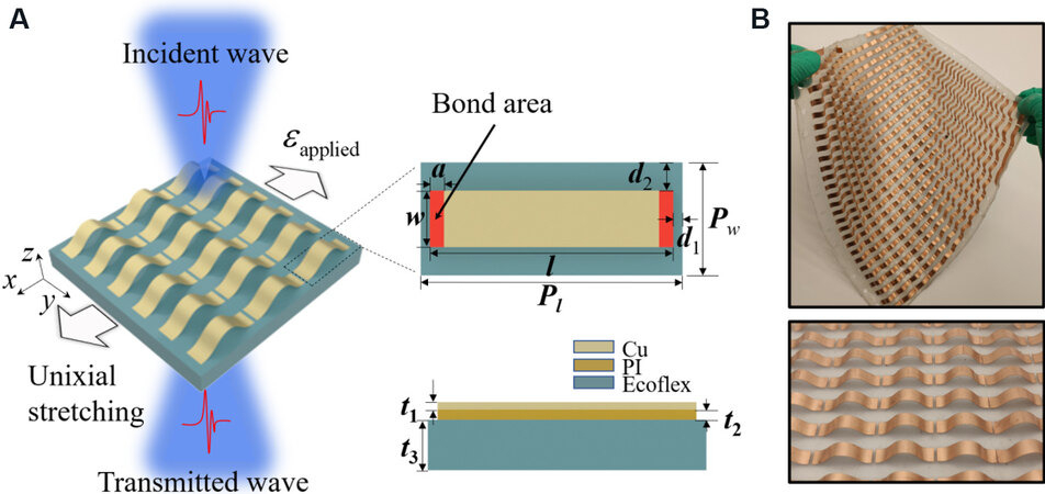
Figure 1. (A) Schematic diagram of FSS irradiated by EM waves and geometry of metal unit cell precursors. (B) Optical image of bended FSS and local magnified detail image. FSS: Frequency selective surface; EM: electromagnetic.
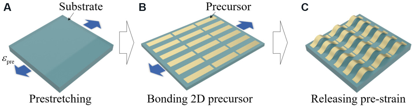
Figure 2. Schematic diagram of fabrication process of frequency selective surface: (A) pre-stretching; (B) bonding 2D precursors; and (C) releasing pre-strain.
In order to study the modulation effect of uniaxial stretching mechanical deformation on the FSS, its transmission performance was investigated by EM experiments and simulations. First, the free-space method EM experiment was designed as shown in Figure 3A, while the EM simulation was obtained by CST simulation software. The transmittance of the EM experiment was calculated with help of the VNA by comparing the EM wave energy irradiated before and after the FSS sample, obtained by Tx ANT and Rx ANT, respectively. The sample was stretched uniaxially at the applied strains by a extensometer, the accuracy of which was guaranteed by the commercially available sliders with scales.
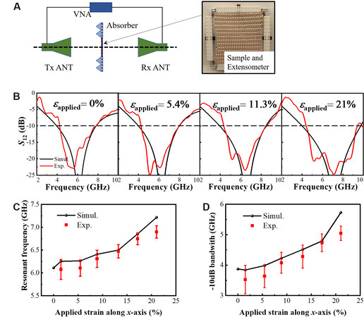
Figure 3. (A) Schematic diagram of EM measurement experiment by the free-space method and an image of the extensometer. (B) EM experimental measurements and simulation results of FSS with uniaxial stretching strains of 0%, 5.4%, 11.3% and 21%, respectively. Trends of (C) resonant frequency and (D) -10 dB bandwidth vs. x-axis uniaxial stretching strains. VNA: Vector network analyzer; EM: electromagnetic.
Figure 3B shows the EM experimental measurements and simulation results when the FSS was uniaxially stretched by 0%, 5.4%, 11.3% and 21%. It can be seen that the EM wave transmittance is in good agreement between the simulations and experiments, indicating the reliable and stable “band resistance” frequency selection performance of the FSS when using mechanical deformation to modulate. Unfortunately, due to the limitations of the imperfect experimental equipment accuracy caused by the small power of the antenna horn and the low dynamic range of the VNA, the experimental data of transmittance less than -25 dB were not measured. However, this does not affect the calculation of the resonant frequency and -10 dB bandwidth, i.e., the two parameters describing the EM properties of the FSS. To further explore the EM modulation effect, the trends in resonant frequency and -10 dB bandwidth vs. x-axis uniaxial stretching strains are depicted in Figure 3C and D. The results show that the resonant frequency and -10 dB bandwidth of the FSS in the unstrained state are 6.1 and 3.9 GHz, respectively. In contrast, the 21% uniaxial stretching strain increases the resonant frequency to 7.25 GHz and the -10 dB bandwidth to 5.5 GHz, with a significant EM tuning effect.
Research on the mechanical deformation law of the unit cell is beneficial to understanding the EM modulation mechanism of FSS with a buckling dipole by uniaxial stretching. The mechanical deformation of the buckling dipole at different uniaxial stretching strains was quantitatively portrayed using finite element analysis in ABAQUS and a uniaxial extension test setup. In the finite element model, the elastic moduli of PI, Cu and ecoflex were 2.5 GPa, 119 GPa and 0.06 MPa, and the relaxation ratios were 0.34, 0.34 and 0.49, respectively[43]. The Cu/PI laminate and ecoflex were modeled via S4R elements and C3D8R elements, respectively. The morphology of the cells at different uniaxial stretching strains were obtained using a laser displacement sensor. Figure 4A illustrates the deflection of the buckling dipole in the z-direction for stretching strains of 0%, 5.4%, 13.2% and 21.0%. It can be seen that as the uniaxial stretching proceeds, the buckling dipole tends to flatten, but the “bell” shape remains similar in appearance. Simultaneously, the maximum deflection in the z-direction gradually decreases, while the copper length gradually increases, as also demonstrated in Figure 4B, which shows the quantitative trends of the FSS period, the copper length and the maximum deflection along the z-direction vs. the uniaxial stretching strains.
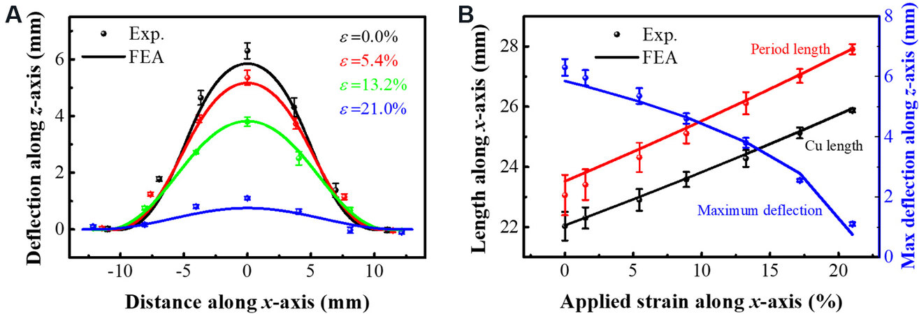
Figure 4. (A) Deflection of buckling dipole in the z-direction for stretching strains of 0%, 5.4%, 13.2% and 21.0%, respectively. (B) Trends in periodic length, Cu length and maximum deflection along the z-direction vs. the uniaxial stretching strains.
The EM modulation mechanism is illustrated by the surface current and the corresponding electric field excited by EM wave irradiation in the FSS, as shown in Figure 5. Figure 5A shows that the surface current is mainly concentrated in the middle of the buckling dipole, oscillating left and right along the dipole arm, when the EM wave at resonant frequency with the electric field direction E along the x-axis is incident on the unstretched FSS. Figure 5B and C show the electric field cloud and vector diagram of the electric field distribution on the FSS surface, respectively, with the electric field concentrated at the gap of the dipole. Figure 5C shows that the electric field intensity above the flexural dipole FSS is large, while the electric field intensity below is relatively small, which indicates that the EM wave at the resonant frequency cannot transmit the band-resistive FSS.
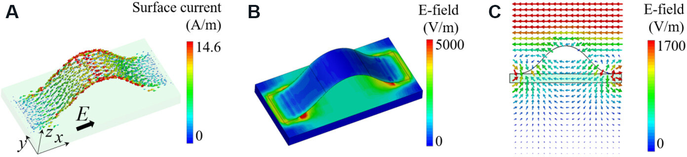
Figure 5. (A) Surface current vector diagram. (B) Electric field distribution and (C) vector diagram on frequency selective surface excited by electromagnetic wave with an x-axis electric field.
The equivalent circuit modeling process and results of the FSS are shown in Figure 6A. The concentration of the electric field and surface currents can be equated as capacitance C1 and inductance L, respectively[44]. The capacitive effect between the cells in the y-direction cannot be ignored and needs to be replaced by capacitance C2 due to the small gap of only 6 mm. The ecoflex dielectric substrate and the free air layer are equated as transmission lines with characteristic impedances Z1 and Z0, respectively. According to transmission line theory[45]:

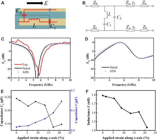
Figure 6. (A) Equivalent circuit modeling process and (B) results of FSS. (C) EM transmittance S21 and (D) reflectance S11 obtained from ADS calculation results, experimental measurements and EM simulation results of the unstretched FSS. Trends in capacitance (E) and inductance (F) vs. uniaxial stretching strains. FSS: Frequency selective surface; ADS: Advanced Design System; EM: electromagnetic.
where Z0 = 377 Ω and εr = 3.4, denoting the relative permittivity constant of the ecoflex substrate[46].
Figure 6B illustrates the FSS equivalent circuit. With the aid of ADS, the L, C1 and C2 values of the equivalent circuit were extracted by fitting the FSS transmittance and reflectance of the buckling dipole calculated by EM simulations. The ADS S-parameter calculation, experimental and EM simulation results of the unstretched FSS are given in Figure 6C and D. The results show good agreement both for reflectivity and transmittance, which strongly suggests that the above equivalent circuit can describe the frequency selection performance of the FSS. Figure 6E and F depict the trends in capacitance and inductance vs. uniaxial stretching strains, respectively. As the FSS is uniaxially stretched, the unit cell gap d1 in the x-axis direction gradually increases, which results in the capacitance C1 remaining lower in the overall trend. However, C2 monotonically increases due to the enhanced capacitive coupling effect between the cells in the y-direction as the stretching due to the flattening of the buckling dipole unit cells and the decreasing maximum deflection. Furthermore, the progressively flattened metal dipole loses the coupling inductance between the 3D metals, resulting in a gradually decreasing inductance L. The modulation of each parameter of the buckling dipole equivalent circuit caused by uniaxial stretching eventually results in a gradual increase in resonant frequency, which is an inevitable consequence of the gradual flattening of the buckling dipole losing the miniaturization characteristics of the 3D FSS from another perspective.
The use of structural parameter analysis to study the tuning effect of the FSS with different sizes after being stretched uniaxially can help to further understand the physical mechanism of actively tuning EM waves by mechanical deformation. As shown in Figure 1A, different sizes of the unit cell of the FSS with half of the gap (d2) in the width direction can significantly change the capacitive coupling effect between unit cells, which have the potential ability to influence the active tuning effect. Figure 7 depict the effect of 21% uniaxial stretching strain on the EM transmission performance of the FSS when d2 is taken to be 1.5, 3.0, 4.5 and 6.0 mm, respectively. It can be seen that the uniaxial stretching strain has a greater active tuning performance when d2 is smaller than 1.5 mm, with a resonant frequency shift of 2.5 GHz. This result helps to parametrically tailor the FSS of a specific size for different tuning purposes in different practical application scenarios.
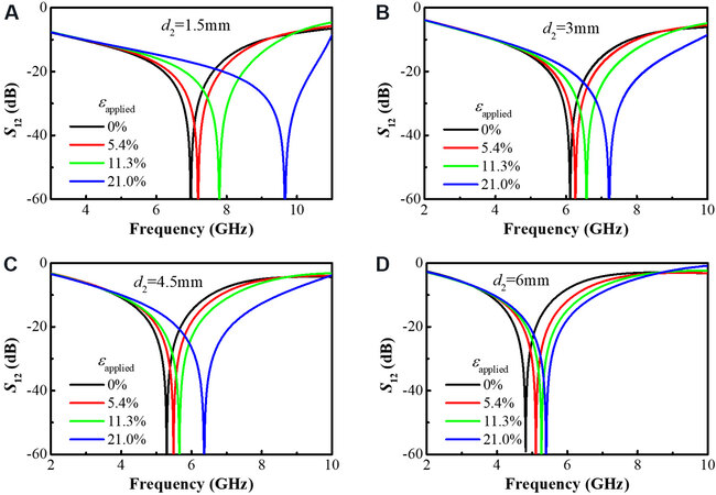
Figure 7. Effect of 21% uniaxial stretching strain on electromagnetic transmission performance of frequency selective surface when d2 is taken as 1.5, 3.0, 4.5 and 6.0 mm, respectively.
CONCLUSIONS
In summary, an FSS with a buckling dipole with continuous modulation of resonant frequency and bandwidth by the mechanical method of uniaxial stretching has been presented. The structure was prepared by a mechanically guided three-dimensional assembly process that has been developed rapidly in recent years. The FSS was obtained by the compression generated from releasing the uniaxial stretching pre-strain on a flexible substrate, which makes the dipole precursor partially attached to it to buckle gradually. The re-uniaxial stretching allows the buckling dipole unit cells to unfold gradually from a 3D to 2D shape. Significant changes in the metal resonance unit shape cause a gradual tuning of the EM properties. The EM experiments, CST simulations and ADS calculations showed consistent results and that 21% uniaxial stretching strain can lead to an increase in the 1.15 GHz resonant frequency and an increase in the -10 dB bandwidth of 1.6 GHz for FSS. The active modulation effect can be significantly influenced by the customized design of the gap in the width direction of the dipole precursor. These studies have revealed that the active modulation of EM waves through mechanical methods could have prospective applications in the fields of EM communication and shielding.
DECLARATIONS
Authors’ contributionsProposing ideas, designing experiments, making samples, completing simulations and writing papers: Fan X
Making samples, completing simulations and writing papers: Pan Z
Proposing the equivalent circuit model: Chen S
Proposing ideas and writing papers: Li Y
Making samples: Zhao Z
Revising papers: Xin Y
Proposing ideas and writing papers: Pan T
Availability of data and materialsNot applicable.
Financial support and sponsorshipThe authors acknowledge the supports from the National Natural Science Foundation of China (Grant No. 11772030, 61901085), the Aeronautical Science Foundation of the PR China (2018ZC51030) and Opening fund of State Key Laboratory of Structural Analysis for Industrial Equipment, Dalian University of Technology (GZ19117).
Conflicts of interestAll authors declared that there are no conflicts of interest.
Ethical approval and consent to participateNot applicable.
Consent for publicationNot applicable.
Copyright© The Author(s) 2021.
REFERENCES
1. Wahid M, Morris SB. Band pass radomes for reduced RCS. IEE Colloquium on Antenna Radar Cross-Section; 1991 May 7; London, UK. IET; 1991. p. 4/1-4/9.
2. Munk BA. Frequency selective surfaces: theory and design. New York: Wiley; 2005.
4. Chen H, Hou X, Deng L. Design of frequency-selective surfaces radome for a planar slotted waveguide antenna. Antennas Wirel Propag Lett 2009;8:1231-3.
5. Wu TK. Four-band frequency selective surface with double-square-loop patch elements. IEEE Trans Antennas Propagat 1994;42:1659-63.
6. Hickey GS, Wu TK. Development and RF evaluation of a four-frequency selective surface spacecraft subreflector antenna. 1996. Available from: http://hdl.handle.net/2014/24306 [Last accessed on 29 Nov 2021].
7. Li B, Shen Z. Wideband 3D frequency selective rasorber. IEEE Trans Antennas Propagat 2014;62:6536-41.
8. Huang H, Shen Z, Omar AA. 3-D absorptive frequency selective reflector for antenna radar cross section reduction. IEEE Trans Antennas Propagat 2017;65:5908-17.
9. Monni S, Bekers DJ, van Wanum M, et al. Limiting frequency selective surfaces. 2009 European Microwave Conference (EuMC); 2009 Sep 29-2009 Oct 1; Rome, Italy. IEEE; 2009. p. 606-9.
10. Nauman M, Saleem R, Rashid AK, Shafique MF. A miniaturized flexible frequency selective surface for X-band applications. IEEE Trans Electromagn Compat 2016;58:419-28.
11. Dewani AA, O'keefe SG, Thiel DV, Galehdar A. Window RF shielding film using printed FSS. IEEE Trans Antennas Propagat 2018;66:790-6.
12. Ghosh S, Srivastava KV. Broadband polarization-insensitive tunable frequency selective surface for wideband shielding. IEEE Trans Electromagn Compat 2018;60:166-72.
13. Sivasamy R, Moorthy B, Kanagasabai M, Samsingh VR, Alsath MGN. A wideband frequency tunable FSS for electromagnetic shielding applications. IEEE Trans Electromagn Compat 2018;60:280-3.
14. Ghosh S, Srivastava KV. Polarization-insensitive single- and broadband switchable absorber/reflector and its realization using a novel biasing technique. IEEE Trans Antennas Propagat 2016;64:3665-70.
15. Su H, Yang B, Liu X, et al. Optically controlled frequency selective surface for millimeter-wave applications. Optically controlled frequency selective surface for millimeter-wave applications; 2012 Jul 8-14; Chicago, IL, USA. IEEE; 2012. p. 1-2.
16. Vallecchi A, Langley RJ, Schuchinsky AG. Bistate frequency selective surfaces made of intertwined slot arrays. IEEE Trans Antennas Propagat 2017;65:3093-101.
17. Su H, Liu X, Li D, et al. Study of optically controlled active frequency selective surfaces with organic semiconductor. 35th International Conference on Infrared, Millimeter, and Terahertz Waves; 2010 Sep 5-10; Rome, Italy. IEEE; 2010. p. 1-2.
18. Dorsey WM, Mcdermitt CS, Bucholtz F, Parent MG. Design and performance of frequency selective surface with integrated photodiodes for photonic calibration of phased array antennas. IEEE Trans Antennas Propagat 2010;58:2588-93.
19. Chen X, Gao J, Fang C, Xu N, Wang Y, Tang Y. Deformable frequency selective surface structure with tuning capability through thermoregulating. Opt Express 2015;23:16329-38.
20. Mias C. Frequency selective surfaces loaded with surface-mount reactive components. Electron Lett 2003;39:724.
21. Mias C. Varactor-tunable and dipole-grid-based frequency-selective surface. Microw Opt Technol Lett 2004;43:508-11.
22. Gianvittorio JP, Zendejas J, Rahmat-Samii Y, Judy JW. MEMS enabled reconfigurable frequency selective surfaces: design, simulation, fabrication, and measurement. IEEE Antennas and Propagation Society International Symposium (IEEE Cat. No.02CH37313); 2002 Jun 16-21; San Antonio, TX, USA. IEEE; 2002. p. 404-7.
23. Bai K, Cheng X, Xue Z, et al. Geometrically reconfigurable 3D mesostructures and electromagnetic devices through a rational bottom-up design strategy. Sci Adv 2020;6:eabb7417.
24. Xu Z, Lin Y. A stretchable terahertz parabolic-shaped metamaterial. Adv Optical Mater 2019;7:1900379.
25. Xu S, Yan Z, Jang KI, et al. Materials science. Assembly of micro/nanomaterials into complex, three-dimensional architectures by compressive buckling. Science 2015;347:154-9.
26. Zhang Y, Yan Z, Nan K, et al. A mechanically driven form of Kirigami as a route to 3D mesostructures in micro/nanomembranes. Proc Natl Acad Sci U S A 2015;112:11757-64.
27. Yan Z, Zhang F, Liu F, et al. Mechanical assembly of complex, 3D mesostructures from releasable multilayers of advanced materials. Sci Adv 2016;2:e1601014.
28. Fu H, Nan K, Bai W, et al. Morphable 3D mesostructures and microelectronic devices by multistable buckling mechanics. Nat Mater 2018;17:268-76.
29. Pang W, Cheng X, Zhao H, et al. Electro-mechanically controlled assembly of reconfigurable 3D mesostructures and electronic devices based on dielectric elastomer platforms. Natl Sci Rev 2020;7:342-54.
30. Zhang Y, Zhang F, Yan Z, et al. Printing, folding and assembly methods for forming 3D mesostructures in advanced materials. Nat Rev Mater 2017:2.
31. Liu F, Chen Y, Song H, et al. High Performance, tunable electrically small antennas through mechanically guided 3D assembly. Small 2019;15:e1804055.
32. Fan X, Li Y, Chen S, Xing Y, Pan T. Mechanical terahertz modulation by skin-like ultrathin stretchable metasurface. Small 2020;16:e2002484.
33. Huang Y, Chen H, Wu J, Feng X. Controllable wrinkle configurations by soft micro-patterns to enhance the stretchability of Si ribbons. Soft Matter 2014;10:2559-66.
34. Cai S, Han Z, Wang F, et al. Review on flexible photonics/electronics integrated devices and fabrication strategy. Sci China Inf Sci 2018;61:060410.
35. Jin B, Song H, Jiang R, Song J, Zhao Q, Xie T. Programming a crystalline shape memory polymer network with thermo- and photo-reversible bonds toward a single-component soft robot. Sci Adv 2018;4:eaao3865.
36. Chen H, Zhu F, Jang KI, et al. The equivalent medium of cellular substrate under large stretching, with applications to stretchable electronics. J Mech Phys Solids 2018;120:199-207.
37. Zhu F, Xiao H, Li H, Huang Y, Ma Y. Irregular hexagonal cellular substrate for stretchable electronics. J Appl Mech 2019;86:034501.
38. Mei Y, Huang G, Solovev AA, et al. Versatile approach for integrative and functionalized tubes by strain engineering of nanomembranes on polymers. Adv Mater 2008;20:4085-90.
39. Guo X, Li H, Ahn BY, et al. Two- and three-dimensional folding of thin film single-crystalline silicon for photovoltaic power applications. Proc Natl Acad Sci U S A 2009;106:20149-54.
40. Zhu J, Tang W, Wang C, Huang C, Shi Y. Dual-polarized bandpass frequency-selective surface with quasi-elliptic response based on square coaxial waveguide. IEEE Trans Antennas Propagat 2018;66:1331-9.
41. Jin C, Lv Q, Wang J, Li Y. Capped dielectric inserted perforated metallic plate bandpass frequency selective surface. IEEE Trans Antennas Propagat 2017;65:7129-36.
42. Jin C, Lv Q, Mittra R. Dual-polarized frequency-selective surface with two transmission zeros based on cascaded ground apertured annular ring resonators. IEEE Trans Antennas Propagat 2018;66:4077-85.
43. Lin X, Pan F, Yang K, et al. A stair-building strategy for tailoring mechanical behavior of re-customizable metamaterials. Adv Funct Mater 2021;31:2101808.
44. Sanders P, Eastman J, Weertman J. Elastic and tensile behavior of nanocrystalline copper and palladium. Acta Materialia 1997;45:4019-25.
Cite This Article
Export citation file: BibTeX | RIS
OAE Style
Fan X, Pan Z, Chen S, Li Y, Zhao Z, Xin Y, Pan T. Design and fabrication of a reconfigurable and flexible frequency selective surface with a buckling dipole via mechanical stretching. Soft Sci 2021;1:13. http://dx.doi.org/10.20517/ss.2021.18
AMA Style
Fan X, Pan Z, Chen S, Li Y, Zhao Z, Xin Y, Pan T. Design and fabrication of a reconfigurable and flexible frequency selective surface with a buckling dipole via mechanical stretching. Soft Science. 2021; 1(3): 13. http://dx.doi.org/10.20517/ss.2021.18
Chicago/Turabian Style
Fan, Xuanqing, Zijian Pan, Sihong Chen, Yuhang Li, Zhao Zhao, Yuxia Xin, Taisong Pan. 2021. "Design and fabrication of a reconfigurable and flexible frequency selective surface with a buckling dipole via mechanical stretching" Soft Science. 1, no.3: 13. http://dx.doi.org/10.20517/ss.2021.18
ACS Style
Fan, X.; Pan Z.; Chen S.; Li Y.; Zhao Z.; Xin Y.; Pan T. Design and fabrication of a reconfigurable and flexible frequency selective surface with a buckling dipole via mechanical stretching. Soft. Sci. 2021, 1, 13. http://dx.doi.org/10.20517/ss.2021.18
About This Article
Copyright

Data & Comments
Data


 Cite This Article 30 clicks

 Like This Article 8
likes
Like This Article 8
likes


Comments
Comments must be written in English. Spam, offensive content, impersonation, and private information will not be permitted. If any comment is reported and identified as inappropriate content by OAE staff, the comment will be removed without notice. If you have any queries or need any help, please contact us at support@oaepublish.com.